Configuration
5.4 Mounting
1FN3 linear motors
150 Configuration Manual, 10/2018, 6SN1197-0AB86-0BP2
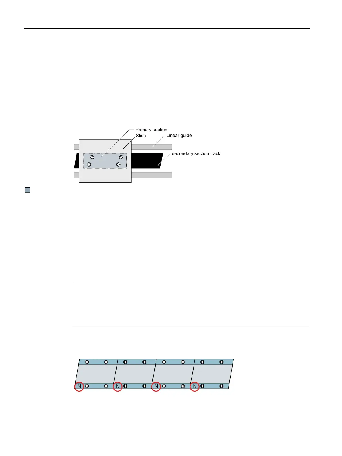
3. Mount the primary section on the slide.
● Secure the slide on the guides.
● Push the slide over the primary section. When doing this, the mounting holes of the
primary section and slide must be fully aligned.
● The mounting screws are initially screwed through the slide into the primary section and
tightened by hand. By uniform and alternating tightening of the mounting screws, the
primary section is lifted from the secondary section track.
● Then remove the spacer foil from the air gap without applying any force.
Assembling individual motor components
Assembly of the secondary sections
Use the mounting screws to force-fit the secondary sections to the machine bed. You screw
in the optional installable heatsink profiles together with secondary sections between the
secondary sections and the machine bed. The mounting dimensions without secondary
section cooling are reduced by the height of the heatsink profiles.
Note
Hole in the machine bed
The shaft of the bolts, which are used to attach the secondary section to the machine base
may not reach the thread.
If necessary, you must lower the relevant hole in the machine bed.
The letter "N" is to be found on each secondary section. Ensure that the letter "N" on each of
the secondary sections is pointing in the same direction, as shown in the following figure.
Figure 5-23 Position of the "N" mark on secondary sections of the 1FN3 product family

 Loading...


