Technical data and characteristics
6.1 Explanations
1FN3 linear motors
170 Configuration Manual, 10/2018, 6SN1197-0AB86-0BP2
Explanations of the characteristic curves
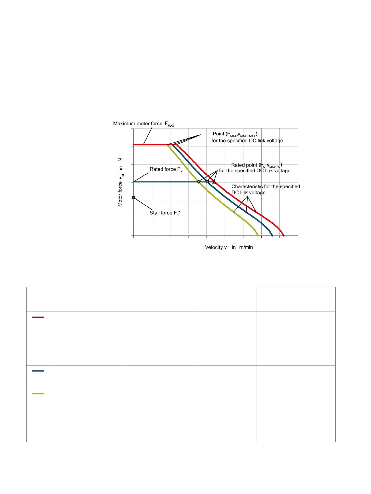
Motor force vs. velocity
The diagrams for motor force F
M
for each of the motors include three characteristics for
various DC link voltages U
DC
or converter output voltages U
a max.
See also the table below
"Color coding of F-v characteristics in the diagrams" and the following figure.
Figure 6-3 Characteristic curve for the motor force F
M
versus velocity v, schematic
Table 6- 1 Color coding of the F-v characteristics in the diagrams
Resulting DC link voltage
U
DC
Converter output voltage
(rms value) U
a max
Permissible line supply
voltage
(rms value)
SINAMICS S120
Line Module
634 V 460 V 480 V Smart Line Module,
non-active with regenerative
feedback
or
Basic Line Module,
non-active without
600 V 425 V 400 V Active Line Module,
active with regenerative
528 V 380 V 400 V Smart Line Module,
non-active with regenerative
feedback
or
Basic Line Module,
non-active without

 Loading...


