Technical data and characteristics
6.1 Explanations
1FN3 linear motors
Configuration Manual, 10/2018, 6SN1197-0AB86-0BP2
169
Primary section main cooler data
Q
P,H,MAX
Maximum thermal output dissipated through the main cooler when utilizing rated force F
N
and at the
rated temperature T
N
P,H,MIN
Recommended minimum volume flow rate through the main cooler to achieve the rated force F
N
ΔT
P,H
Temperature rise of the coolant between the flow and return lines of the main cooler at the operating
point (Q
P,H,MAX
,V
P,H,MIN
)
Δp
P,H
Pressure drop of the coolant between the flow and return lines of the main cooler with flow rate V
P,H,MIN
Primary section precision cooler data
Q
P,P,MAX
Maximum thermal output dissipated through the primary section precision cooler when utilizing rated
N
and at the rated temperature T
N
V
P,P,MIN
Recommended minimum volume flow rate in the primary section precision cooler so that the maxi-
mum surface temperature is T
VORL
+ 4 K
Δp
P,P
Pressure drop of the coolant between the flow and return lines of the primary section precision cooler
P,P,MIN
Secondary section cooling data
Q
S,MAX
Maximum thermal output dissipated through the secondary section cooling system when the rated
N
N
Recommended minimum volume flow rate in the secondary section cooling
Δp
S
Pressure drop of the coolant between the flow and return lines of the secondary section cooling with a
flow rate V
S,MIN
and a reference length of one meter
Δp
KS
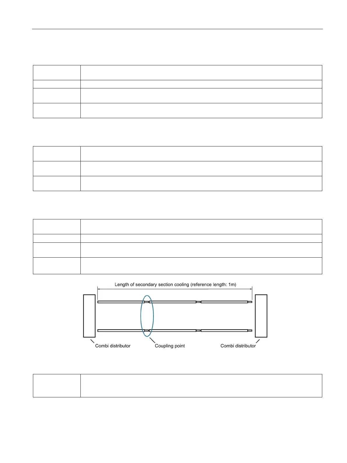
Pressure drop of the coolant at a coupling point of the secondary section cooling
Comment: For the term "coupling point", see the following figure.
Figure 6-2 Components of the standard secondary section cooling system, schematic
Δp
KV
Pressure drop of the coolant in a combi distributor
Usually two combi distributors are used in the secondary section cooling, see the following

 Loading...


