Technical data and characteristics
6.1 Explanations
1FN3 linear motors
168 Configuration Manual, 10/2018, 6SN1197-0AB86-0BP2
k
F,20
Force constant of the motor with a rated air gap and a secondary section temperature of 20 °C.
The force constant refers to the linear (lower) section of the motor force-current
k
E
Voltage constant for calculating the mutually induced voltage between the phase and the star point
k
M,20
Motor constant at a winding temperature of 20 °C.
The motor constant k
M
can be calculated for other temperatures:
k
M
(T) = k
M,20
[1 + α(T - 20 °C)] with the temperature coefficients α = 0.001 1/K for the magnets used.
R
STR,20
Line resistance of the winding at a winding temperature of 20 °C.
The line resistance R
STR
can be calculated for other temperatures:
STR
STR,20
[1 + α(T - 20 °C)] with the temperature coefficients α = 0.00393 1/K for copper.
Phase inductance of the winding with a rated air gap.
A
Attraction force between the primary section and the secondary section with a rated air gap.
t
TH
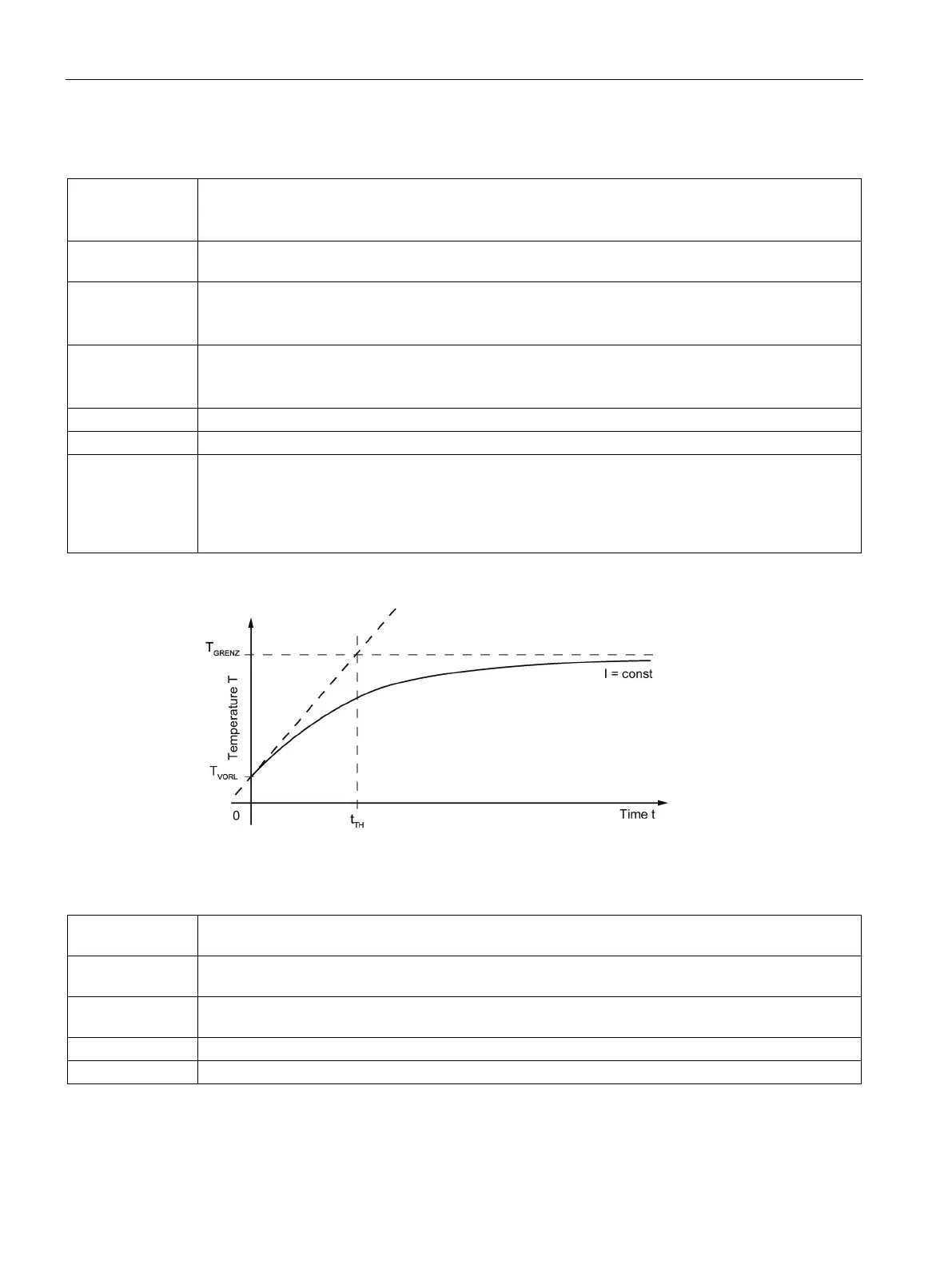
Thermal time constant of the motor winding
The thermal time constant is obtained from the temperature characteristic in the motor
winding for a sudden load with constant current at time t = 0,, see the following figure. After time t
TH
has elapsed, the motor winding reaches approx. 63% of its final temperature T
GRENZ
, if the
temperature protection does not respond beforehand.
Figure 6-1 Definition of the thermal time constant
τ
M
Pole width of the motor, corresponds to the distance between the respective centers of the north and
south poles of neighboring magnets on a secondary section.
m
P
Mass of the primary section without precision cooler, mounting screws, plugs, connection cables and
m
P,P
Mass of the primary section with precision cooler, but without mounting screws, plugs, connection
S
Mass of a secondary section without mounting screws, cover and optional heatsink profiles
Mass of a secondary section with heatsink profiles, but without mounting screws, cover and coolant

 Loading...


