Configuration
5.2 Configuring workflow
1FN3 linear motors
112 Configuration Manual, 10/2018, 6SN1197-0AB86-0BP2
The inertia forces that result from the sequence of motion and that the motor must
compensate for, are proportional to the acceleration a and the dynamic mass m:
F
a
= m ‧ a
They oppose the direction of acceleration.
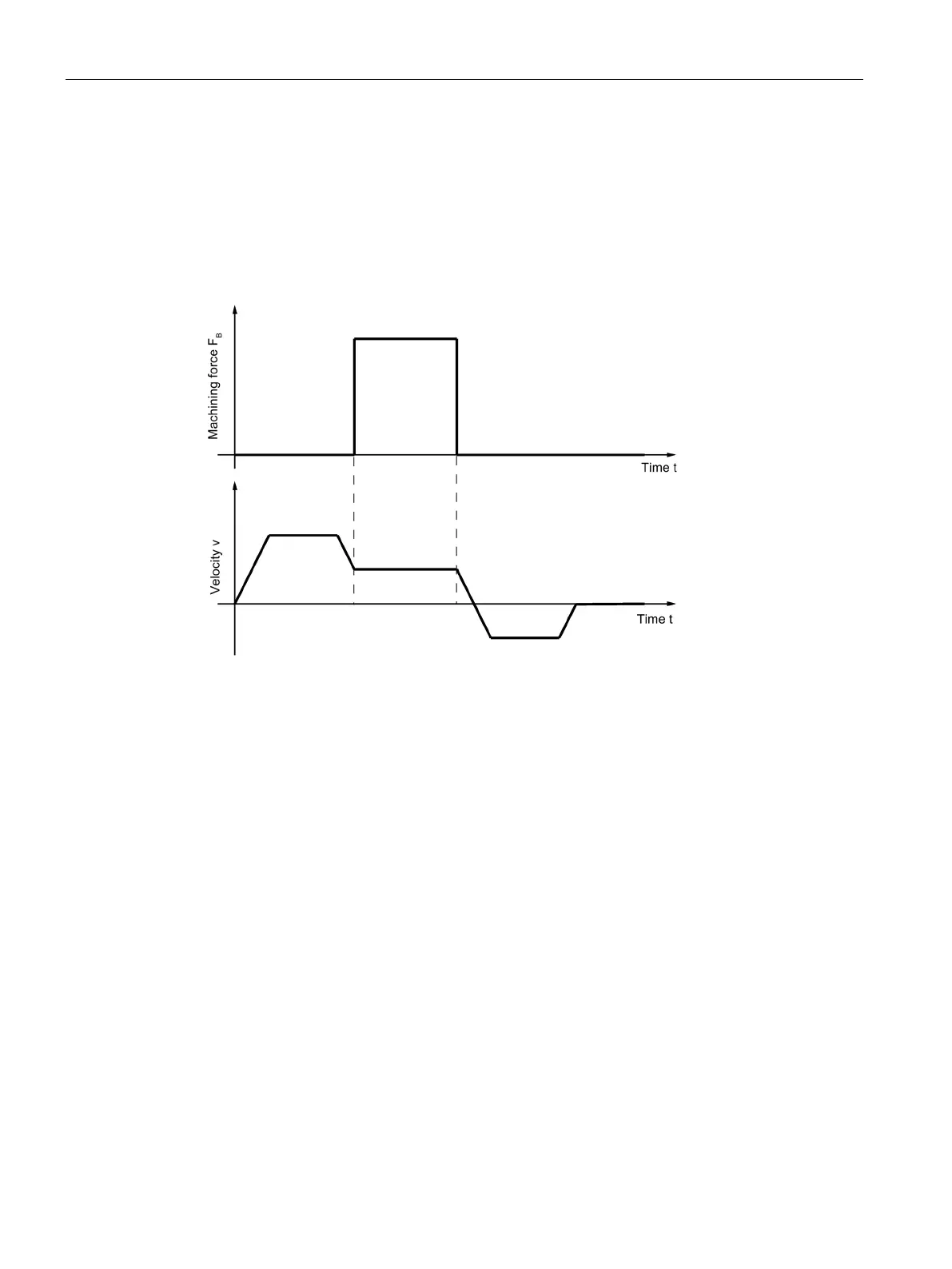
A
machining force
- time diagram for a motor could look like the following figure.
The velocity-time diagram serves as a comparison.
Figure 5-6 Example of a machining force-time diagram

 Loading...


