Electrical connection
8.3 System integration
1FN3 linear motors
Configuration Manual, 10/2018, 6SN1197-0AB86-0BP2
491
Peak load motors from this series are also available with a combined cable. Connect the
combined cable via a connection cover with PG cable gland on the terminal panel.
Separate power and signal cables with their own connectors make electrical connection
simpler, for example to a SME12x Sensor Module. You also avoid use of a terminal block.
Combined cable for the power and temperature sensor connection
As standard, this connection type is only intended for peak load motors. Continuous load
motors can be upgraded as required. The combined cable has 4 power cores (3 phases and
PE) and 2x2 signal cores for the temperature sensors. Connect the combined cable directly
at the integrated terminal panel. Use angled ring cable lugs for the ends of the cables.
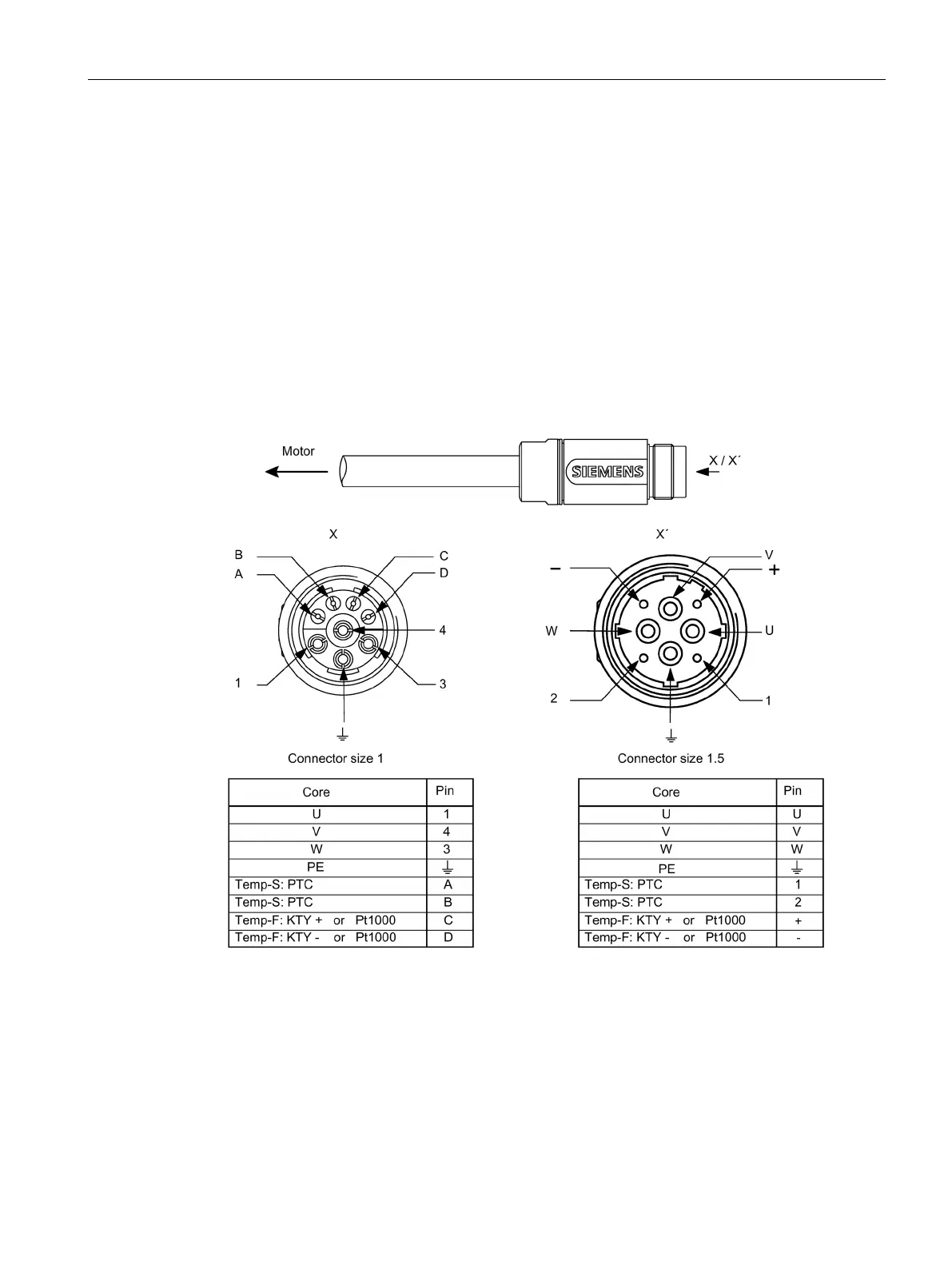
You will find connection types for connection of temperature sensors and core assignments
in Chapter "Signal connection (Page 500)".
Figure 8-6 PIN assignments of the plug-in connectors for combined cables
Connect the cables at the motor end with EMC-compliant metallic PG cable glands. This
allows cable connections with low bending radii in all directions.

 Loading...


