Mechanical properties
3.1 Cooling
1FN3 linear motors
62 Configuration Manual, 10/2018, 6SN1197-0AB86-0BP2
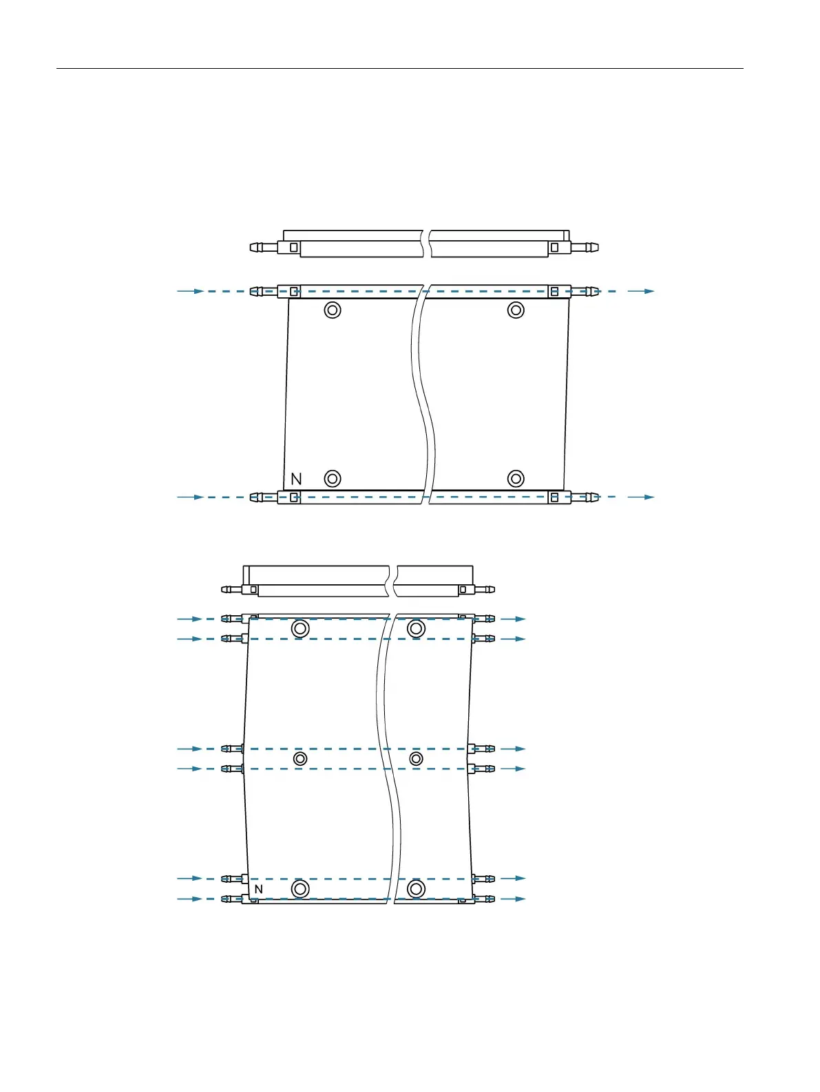
The heatsink profiles are laid between the machine base and the secondary sections and
together with these screwed to the machine base. The following two figures show the
resulting cooling system without secondary section end pieces. The blue dotted lines
indicate the coolant flow.
Figure 3-2 Secondary section cooling, comprising heatsink profiles with hose connector nipples for
motors of sizes 1FN3050 … 1FN3450 (side view and top view)
Figure 3-3 Secondary section cooling, comprising heatsink profiles with hose connector nipples for
motors of sizes 1FN3600 … 1FN3900 (side view and top view)

 Loading...


