Commands Calling Axis Movements
2.1 Interpolation commands
04.07
2-28
© Siemens AG 2007 All rights reserved
SINUMERIK 802D sl/840D/840D sl/840Di/840Di sl/810D ISO Milling (PGM) -- 04.07 Edition
If an optional linear 5th-axis is selected, circular interpolation is possible in the Xβ,
Zβ,orYβ plane which includes the 5th-axis in addition to the XY, YZ, and ZX pla-
nes. (β=U,V,orW)
S Circular interpolation in Xβ plane
G17 G02 (or G03) X ⋅⋅⋅ β ⋅⋅⋅ R ⋅⋅⋅ (or I ⋅⋅⋅ J ⋅⋅⋅)F⋅⋅⋅;
S Circular interpolation in Zβ plane
G18 G02 (or G03) Z ⋅⋅⋅ β ⋅⋅⋅ R ⋅⋅⋅ (or K ⋅⋅⋅ I ⋅⋅⋅)F⋅⋅⋅;
S Circular interpolation in Yαβ plane
G19 G02 (or G03) Y ⋅⋅⋅ β ⋅⋅⋅ R ⋅⋅⋅ (or J ⋅⋅⋅ K ⋅⋅⋅)F⋅⋅⋅;
S If address characters which represent the 4th- and 5th-axis are omitted as with
the commands of “G17 G02 X ⋅⋅⋅ R ⋅⋅⋅ (or I ⋅⋅⋅ J ⋅⋅⋅)F⋅⋅⋅ ;” the XY
plane is automatically selected for the interpolation plane. Circular interpolation
with the 4th or 5th axis is not possible if these additional axes are rotary axes.
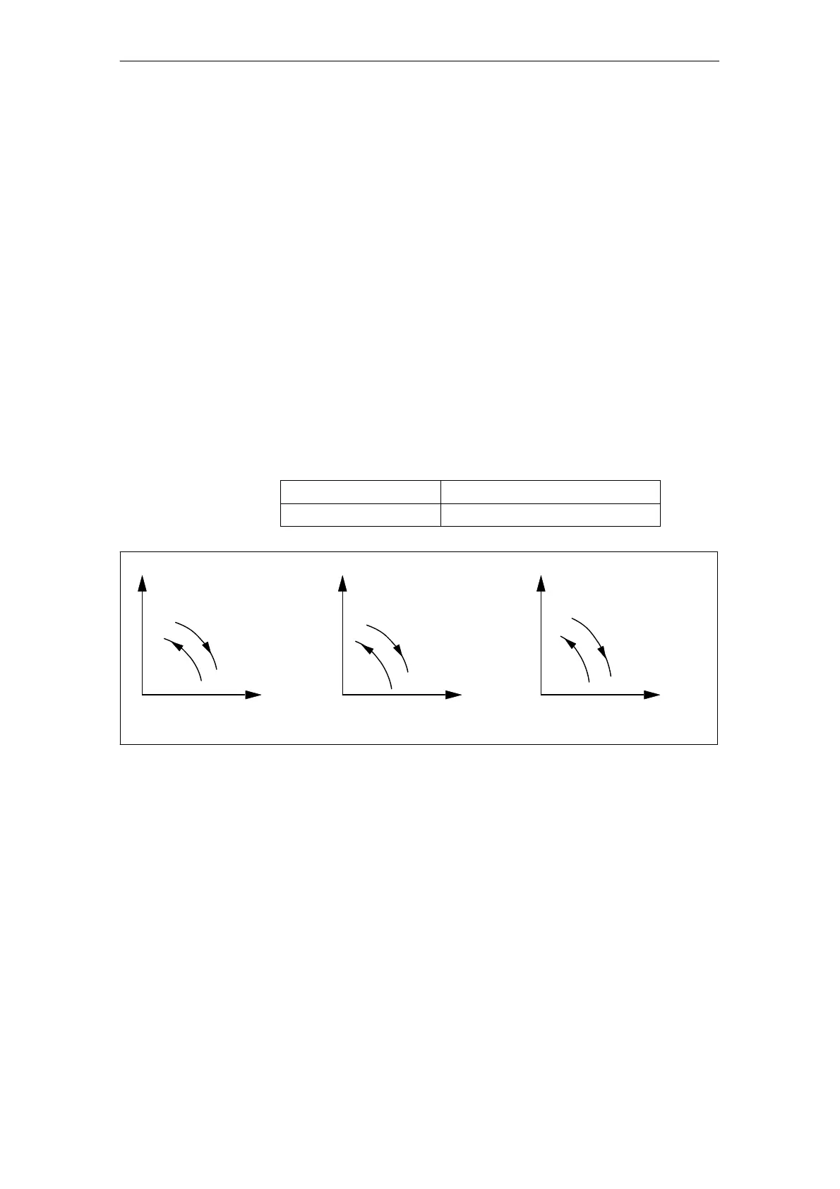
Rotation direction
The direction of arc rotation should be specified in the manner indicated in Fig. 2-3.
G02 Clockwise direction (CW)
G03 Counterclockwise direction (CCW)
Y-axis
G02
G03
X-axis
XY plane
(G17)
X-axis
G02
G03
G02
G03
Z-axis
ZX plane
(G18)
Z-axis
Y-axis
YZ plane
(G19)
Fig. 2-3 Rotation direction of circular arc
End point
The end point can be specified in either absolute or incremental values correspon-
ding to the designation of G90 or G91 (not in G code system A).

 Loading...


