Detailed Description
2.3 Coordinate systems
Axis Types, Coordinate Systems, Frames (K2)
2-28 Function Manual, 08/2005 Edition, 6FC5397-0BP10-0BA0
2.3.4 Additive offsets
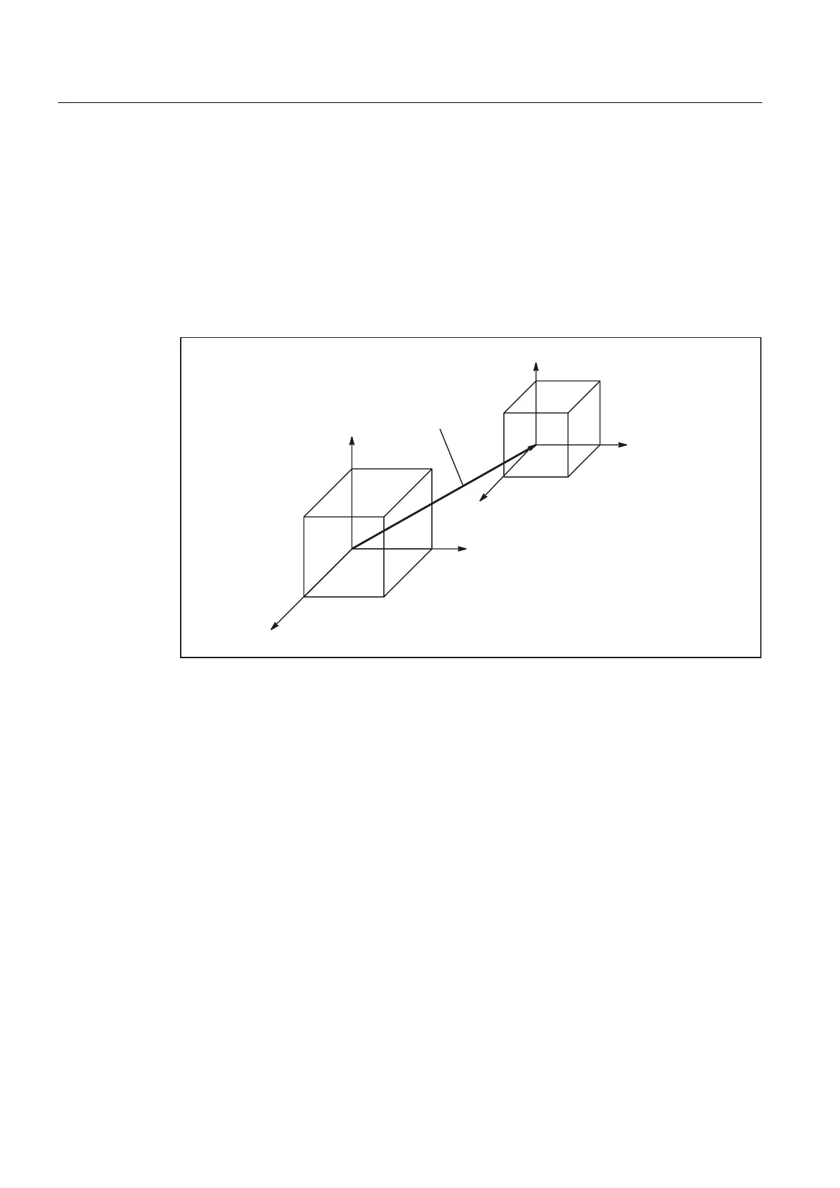
Zero offsets external
The "Zero offset external" is an axial offset. Unlike with frames, no components for rotation,
scaling and mirroring are possible.
;
=
<
;
<
=
%DVLFFRRUGLQDWHV\VWHP%&6
%DVLF]HURV\VWHP%=6
=HURRIIVHWH[WHUQDO
Fig. 2-17 Zero offset external between BCS and BZS
Setting the offset values
The offset values are set:
• PLC
By describing system variables
• Via the operator panel
From menu "Current zero offsets"
• NC Program
By assigning to system variable $AA_ETRANS[axis]
Activation of the offset values
The 0/1 edge of the PLC signal "Accept external zero offset" (DB31 to DBX3.0) activates the
previously defined offset values. The 0/1 edge change is only evaluated in Automatic
operating mode.

 Loading...


