<_EW>, <_FS>, <_ZFS>, <_TR>, <_DR>, <_UMODE>, <_GMODE>, <_DMODE>,
<_AMODE>)
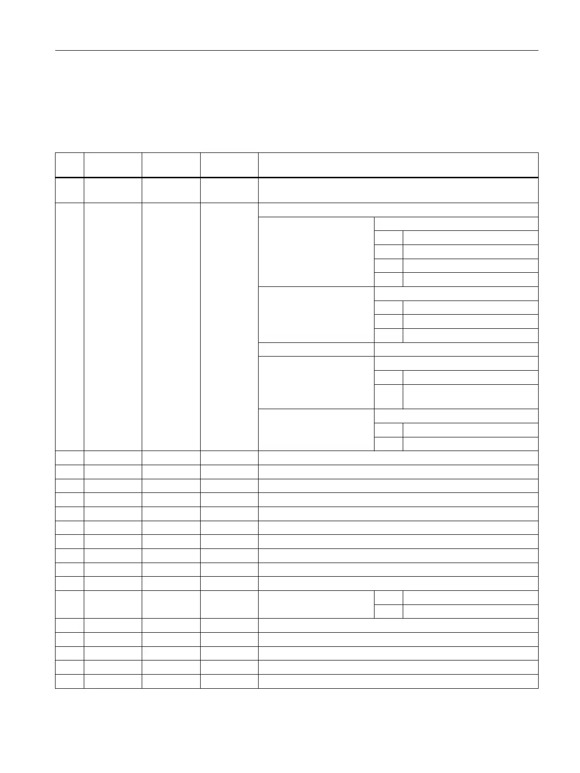
Parameters
No. Parameter
mask
Parameter
internal
Data type Meaning
1 PRG <_PRG> STRING
[100]
Name of removal program
2 <_VARI> INT Machining type
UNITS: Machining process
1 = Roughing
3 = Base finishing
4 = Edge finishing
5 = Chamfering
TENS: Infeed type
0 = Central insertion
1 = Helical insertion
2 = Oscillating insertion
HUNDREDS: Reserved
THOUSANDS: Lift mode
0 = Lift off to retraction plane
1 = Lift off to reference point + safety
clearance
TEN THOUSANDS: Start point for roughing and finishing base
0 = Auto
1 = Manual
3 RP <_RP> REAL Retraction plane (abs)
4 Z0 <_Z0> REAL Reference point of tool axis (abs)
5 SC <_SC> REAL Safety clearance (to be added to reference point, enter without sign)
6 Z1 <_Z1> REAL Final depth (see <_AMODE> UNITS)
7 F <_F> REAL Feedrate in the plane during roughing/finishing
8 FZ <_FZ> REAL Depth infeed rate
9 DXY <_DXY> REAL Infeed plane - unit (see <_AMODE> TENS)
10 DZ <_DZ> REAL Depth infeed
11 UXY <_UXY> REAL Finishing allowance, plane
12 UZ <_UZ> REAL Finishing allowance, depth
13 <_CDIR> INT Milling direction 0 = Down-cut
1 = Up-cut
14 XS <_XS> REAL Starting point X, absolute
15 YS <_YS> REAL Starting point Y, absolute
16 ER <_ER> REAL Helical insertion: Radius
17 EP <_EP> REAL Helical insertion: Pitch
18 EW <_EW> REAL Oscillating insertion: Maximum insertion angle
Work preparation
3.25 Programming cycles externally
NC programming
Programming Manual, 12/2019, 6FC5398-2EP40-0BA0 1047
 Loading...


