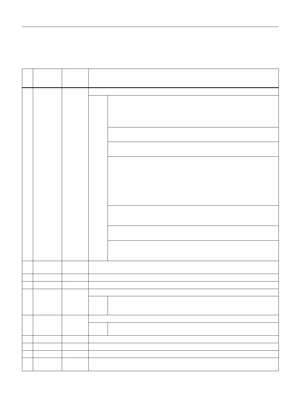
Table 3-8 CYCLE973 call parameters
1)
No. Screen
form param‐
eter
Cycle pa‐
rameter
Meaning
1 S_MVAR Measuring variant (default=0012103)
Val‐
ues:
UNITS: Calibration on a surface, edge or in a groove
0 = Length on surface/edge (in the WCS) with known setpoint
1 = Radius on surface (in the WCS) with known setpoint
2 = Length in groove (in the WCS), see S_CALNUM
3 = Radius in groove (in the WCS), see S_CALNUM
TENS: Reserved
0 = 0
HUNDREDS: Reserved
0 = 0
THOUSANDS: Selection of measuring axis and measuring direction for calibra‐
tion
2)
0 = No specification (for surface calibration on the groove base, no selection of the
measuring axis and measuring direction)
4)
1 = Specify selection of measuring axis and measuring direction, see S_MA, S_MD
(one measuring direction in a measuring axis)
2 = Specify selection of measuring axis, see S_MA (two measuring directions in a
measuring axis)
TEN THOUSANDS: Determination of the positional deviation (probe skew)
2), 3)
0 = Determine positional deviation
1 = Do not determine positional deviation
HUNDRED THOUSANDS: Reserved
0 = 0
ONE MILLION:adapt tool length
7)
0 = Do not adapt tool length (only trigger points)
1 = Adapt tool length
2 Icon+
number
S_PRNUM Number of the field of the probe parameters (not probe number)
(default=1)
3 S_CALNUM Number of the calibration groove for calibration on a groove (default=1)
5)
4 S_SETV Setpoint for calibration on a surface
5 X0 S_MA Measuring axis (number of the axis)
6)
(default=1)
Val‐
ues:
1 = 1st axis of the plane (for G18 Z)
2 = 2nd axis of the plane (for G18 X)
3 = 3rd axis of the plane (for G18 Y)
6)
6 +- S_MD Measuring direction (default=1)
Val‐
ues:
0 = Positive measuring direction
1 = Negative measuring direction
7 DFA S_FA Measurement path
8 TSA S_TSA Safe area
9 VMS S_VMS Variable measuring velocity for calibration
2)
10 Measure‐
ments
S_NMSP Number of measurements at the same location
2)
(default=1)
Work preparation
3.25 Programming cycles externally
NC programming
1156 Programming Manual, 12/2019, 6FC5398-2EP40-0BA0
 Loading...


