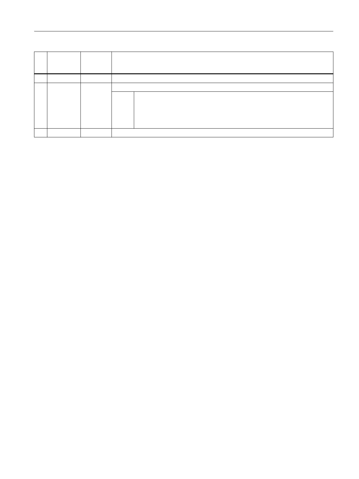
No. Screen
form param‐
eter
Cycle pa‐
rameter
Meaning
11 S_MCBIT Reserved
12 _DMODE Display mode
Val‐
ues:
UNITS: Machining plane G17/G18/G19
0 = Compatibility, the plane active before the cycle call remains active
1 = G17 (only active in the cycle)
2 = G18 (only active in the cycle)
3 = G19 (only active in the cycle)
13 _AMODE Alternative mode
1)
All default values = 0 or marked as default=x
2)
Display depends on the general SD54760 $SNS_MEA_FUNCTION_MASK_PIECE
3)
Only relevant for calibration in two axis directions
4)
Only measuring axis and measuring direction are determined automatically from the cutting edge position (SL) of the probe.
SL=8 → -X , SL=7 → -Z
5)
The number of the calibration groove (n) refers to the following general setting data (all positions in MCS):
For cutting edge position SL=7:
SD54615 $SNS_MEA_CAL_EDGE_BASE_AX1[n] Position of the bottom of the groove in the 1st axis of the plane (for G18 Z)
SD54621 $SNS_MEA_CAL_EDGE_PLUS_DIR_AX2[n] Position of the groove side in the plus direction of the 2nd axis of the
plane (for G18 X)
SD54622 $SNS_MEA_CAL_EDGE_MINUS_DIR_AX2[n] Position of the groove side in the minus direction of the 2nd axis
of the plane
For cutting edge position SL=8:
SD54619 $SNS_MEA_CAL_EDGE_BASE_AX2[n] Position of the bottom of the groove in the 2nd axis of the plane
SD54620 $SNS_MEA_CAL_EDGE_UPPER_AX2[n] Position of the upper edge of the groove in the 2nd axis of the plane
(only for prepositioning of the probe)
SD54617 $SNS_MEA_CAL_EDGE_PLUS_DIR_AX1[n] Position of the groove side in the plus direction of the 1st axis of the
plane
SD54618 $SNS_MEA_CAL_EDGE_MINUS_DIR_AX1[n] Position of the groove side in the minus direction of the 1st axis of
the plane
Note:
The position values for the groove wall +- can be determined roughly.
The groove width from the difference of the position values of the groove wall must be determined precisely (precision dial
gauge).
For calibration in the groove, it is assumed that the tool length of the probe of the calibrated axis = 0.
The positions values for the groove base must also be determined precisely on the machine (no drawing dimensions).
6)
Measuring axis S_MA=3 for calibration on a surface and on a turning machine with real 3rd axis of the plane (for G18 Y).
7)
Adapt tool length when calibrating length in the groove, or for lengths at the surface.
Workpiece probe in lathes can be defined using 2 lengths (X Z).
Turning probe, type 580
cutting-edge position 7: For length calibration, optionally, the Z length is corrected.
Turning probe, type 580
cutting edge position 8: For length calibration, optionally, the X length is corrected
The tool length is not adapted for the measurement version, radius at groove or radius at the surface.
Only the corresponding trigger points are saved.
Work preparation
3.25 Programming cycles externally
NC programming
Programming Manual, 12/2019, 6FC5398-2EP40-0BA0 1157

 Loading...


