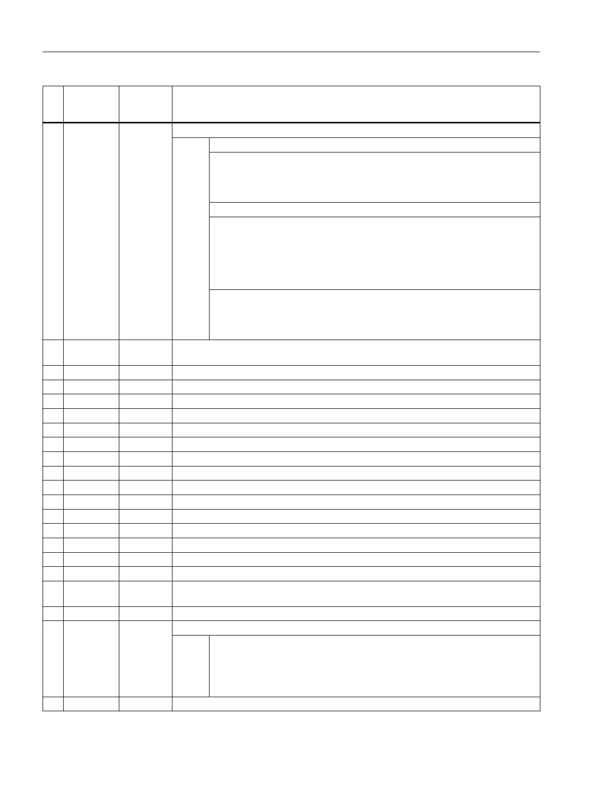
No
.
Screen
form pa‐
rameter
Cycle pa‐
rameter
Meaning
2 Selection S_KNUM Correction in work offset (WO) or basic or basic reference
3)
Val‐
ues:
UNITS:
TENS:
0 = No correction
1 to max. 99 numbers of the work offset or
1 to max. 16 numbers of the basic offset
HUNDREDS: Reserved
THOUSANDS: Correction in WO or basic WO or basic reference
0 = Correction in adjustable WO
1 = Correction in channel-specific basic WO
2 = Correction in basic reference
3 = Correction in global basic WO
7)
9 = Correction in active WO or for G500 in last active channel-specific basic WO
TEN THOUSANDS: Correction in WO or basic WO or basic reference coarse or
fine
0 = Fine correction
6)
1 = Coarse correction
3 Icon+
number
S_PRNUM Number of the field of the probe parameters (not probe number)
(value range 1 to 40)
4 S_SETV Diameter of the ball(s)
4)
5 DFA S_FA Measurement path
6 TSA S_TSA Safe area
7 alpha 0 S_STA1 Starting angle for measurement at an angle
8 alpha 1 S_INCA Incremental angle for measurement at an angle
9 X1 S_SETV0 Set position of the 1st ball of the 1st axis of the plane (for G17 X) for measuring 3 balls
10 Y1 S_SETV1 Set position of the 1st ball of the 2nd axis of the plane (for G17 Y) for measuring 3 balls
11 Z1 S_SETV2 Set position of the 1st ball of the 3rd axis of the plane (for G17 Z) for measuring 3 balls
12 X2 S_SETV3 Set position of the 2nd ball of the 1st axis of the plane for measuring 3 balls
13 Y2 S_SETV4 Set position of the 2nd ball of the 2nd axis of the plane for measuring 3 balls
14 Z2 S_SETV5 Set position of the 2nd ball of the 3rd axis of the plane for measuring 3 balls
15 X3 S_SETV6 Set position of the 3rd ball of the 1st axis of the plane for measuring 3 balls
16 Y3 S_SETV7 Set position of the 3rd ball of the 2nd axis of the plane for measuring 3 balls
17 Z3 S_SETV8 Set position of the 3rd ball of the 3rd axis of the plane for measuring 3 balls
18 TVL S_TNVL Limit value for distortion of the triangle (sum of the deviations) for measuring 3 balls
5)
19 Measure‐
ments
S_NMSP Number of measurements at the same location
2)
(value range 1 to 9)
20 S_MCBIT Reserved
21 _DMODE Display mode
Val‐
ues:
UNITS: Machining plane G17/G18/G19
0 = Compatibility, the plane active before the cycle call remains active
1 = G17 (only active in the cycle)
2 = G18 (only active in the cycle)
3 = G19 (only active in the cycle)
22 _AMODE Alternative mode
Work preparation
3.25 Programming cycles externally
NC programming
1182 Programming Manual, 12/2019, 6FC5398-2EP40-0BA0
 Loading...


