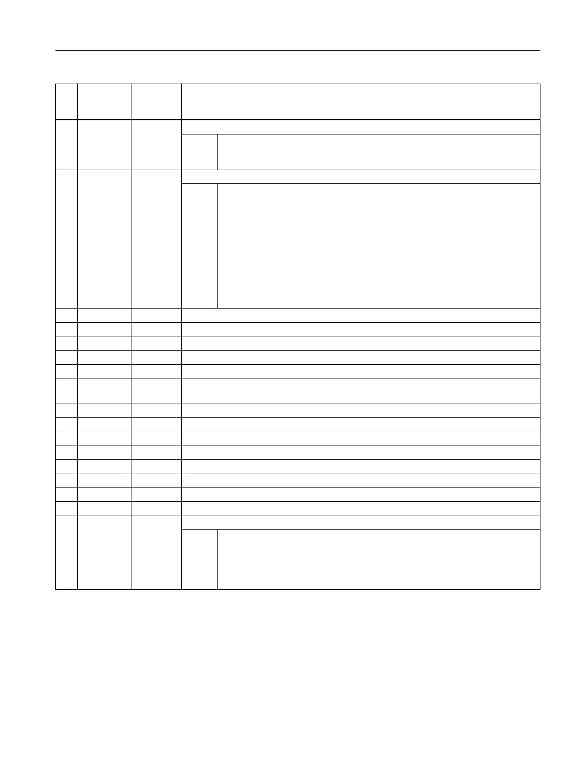
No. Screen
form pa‐
rameter
Cycle pa‐
rameter
Meaning
5 +- S_MD Measuring direction
Val‐
ues:
0 = No selection (measuring direction is determined from actual value)
1 = Positive
2 = Negative
6 V S_ID Offset
Val‐
ues:
0 = For tools without offset
>0 =
● Calibration: The offset is applied to the 3rd axis of the plane (for G17 Z) if the
diameter of the calibration tool is greater than the upper diameter of the probe.
The tool is offset by the tool radius from the center of the probe, minus the value
of S_ID. The offset axis is also specified in S_MA .
● Measure: With multiple cutting edges, the offset of tool length and the highest
point of the cutting edge must be specified for radius measurement or the offset
of tool radius to the highest point of the cutting edge must be specified when
measuring the length.
7 DFA S_FA Measurement path
8 TSA S_TSA Safe area
9 VMS S_VMS Variable measuring velocity for calibration
2)
10 TZL S_TZL Work offset (only for tool measurement)
11 DIF S_TDIF Dimensional difference check for tool measurement (S_MVAR=xx1 or S_MVAR=xx2)
12 Measure‐
ments
S_NMSP Number of measurements at the same location
2)
13 F1 S_F1 1st feedrate for contact with rotating spindle
2)
14 S1 S_S1 1st speed for contact with rotating spindle
2)
15 F2 S_F2 2nd feedrate for contact with rotating spindle
2)
16 S2 S_S2 2nd speed for contact with rotating spindle
2)
17 F3 S_F3 2nd feedrate for contact with rotating spindle
3)
18 S3 S_S3 2nd speed for contact with rotating spindle
3)
19 EVN S_EVNUM Number of the empirical value memory
2)
20 S_MCBIT Screen form of the _CBITs or _CHBITs
21 _DMODE Display mode
Val‐
ues:
UNITS: Machining plane G17/G18/G19
0 = Compatibility, the plane active before the cycle call remains active
1 = G17 (only active in the cycle)
2 = G18 (only active in the cycle)
3 = G19 (only active in the cycle)
Work preparation
3.25 Programming cycles externally
NC programming
Programming Manual, 12/2019, 6FC5398-2EP40-0BA0 1193
 Loading...


