Note
With continuous-path mode G64, the blocks are linked by the look-ahead velocity control in
such a way that there are no velocity jumps.
Direction of rotation of the thread
The direction of rotation of the thread is determined by the direction of rotation of the spindle:
● Clockwise with M3 produces a right-hand thread
● Counter-clockwise with M4 produces a left-hand thread
Syntax
Cylinder thread:
G33 Z… K…
G33 Z… K… SF=…
Face thread:
G33 X… I…
G33 X… I… SF=…
Tapered thread:
G33 X… Z… K…
G33 X… Z… K… SF=…
G33 X… Z… I…
G33 X… Z… I… SF=…
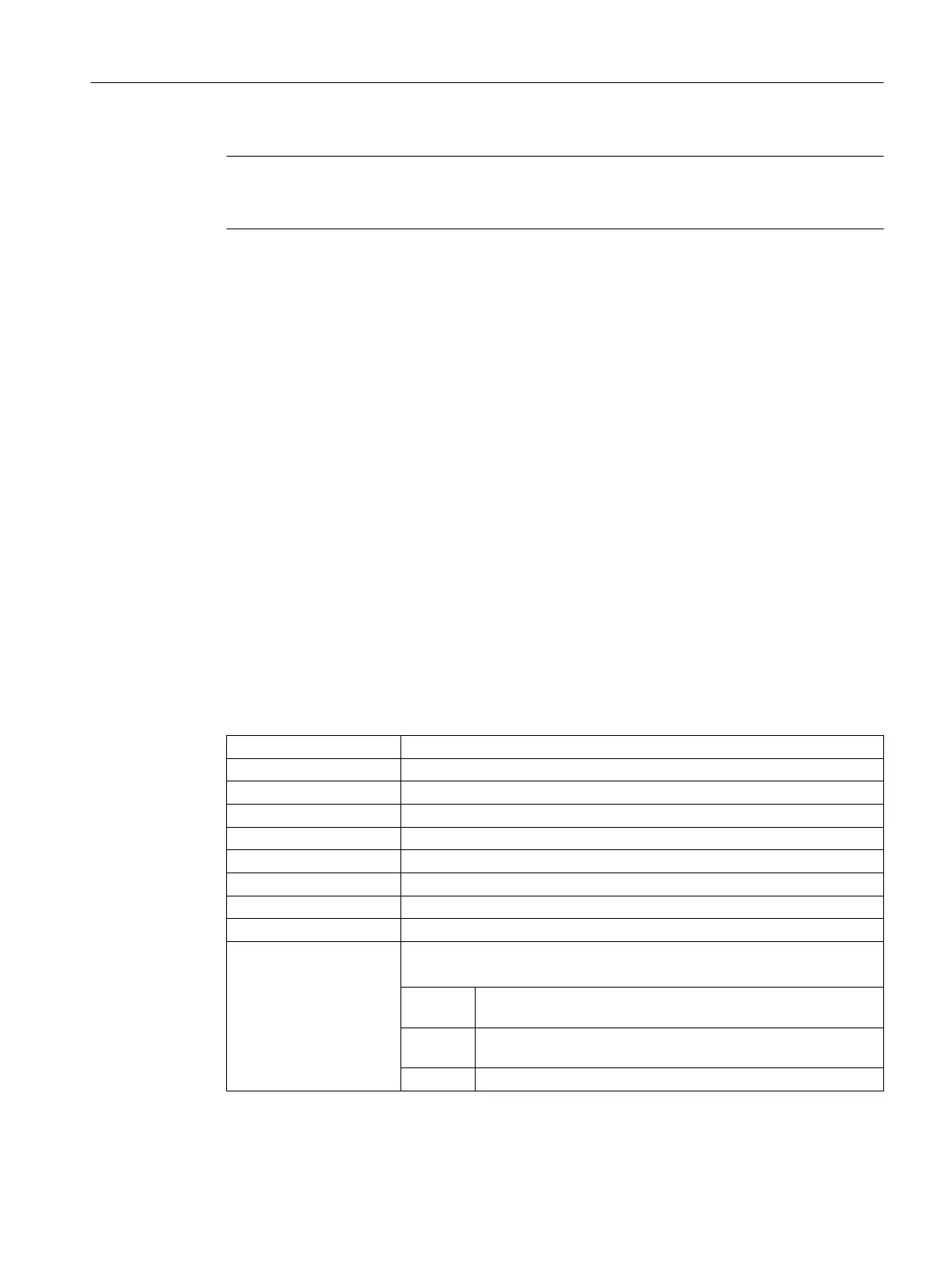
Meaning
G33: Command for thread cutting with constant lead
X... Y... Z... : End point(s) in Cartesian coordinates
I... : Thread lead in X direction
J... : Thread lead in Y direction
K... : Thread lead in Z direction
Z: Longitudinal axis
X: Transverse axis
Z... K... : Thread length and lead for cylinder threads
X... I... : Thread diameter and thread lead for face threads
I... or K... : Thread lead for tapered threads
The specification (I... or K...) refers to the taper angle:
< 45°: The thread lead is specified with K... (thread lead in longitu‐
dinal direction).
> 45°: The thread lead is specified with I.. (thread lead in transverse
direction).
= 45°: The thread lead can be specified with I... or K....
Fundamentals
2.9 Motion commands
NC programming
Programming Manual, 12/2019, 6FC5398-2EP40-0BA0 223
 Loading...


