Example 8
Program code Comment
N10 DEF REAL _CORVAL[3]
N20 $TC_DP1[1,1]=500 ; turning tool
N30 $TC_DP3[1,1]=10.0 ; geometry L1
N40 $TC_DP4[1,1]=15.0 ; geometry L2
N50 $TC_DP5[1,1]=20.0 ; geometry L3
N60 $TC_DP12[1,1]=10.0 ; wear L1
N70 $TC_DP13[1,1]=0.0 ; wear L2
N80 $TC_DP14[1,1]=0.0 ; wear L3
N90 $SC_WEAR_SIGN=TRUE
N100 _CORVAL[0]=10.0
N110 _CORVAL[1]=15.0
N120 _CORVAL[2]=5.0
N130 ROT Y-30
N140 T1 D1 G18 G0
N150 R1=SETTCOR(_CORVAL,"W",1,1)
N160 T1 D1 X0 Y0 Z0 ; ==> MCS position X7.990 Y25.000 Z31.160
N170 M30
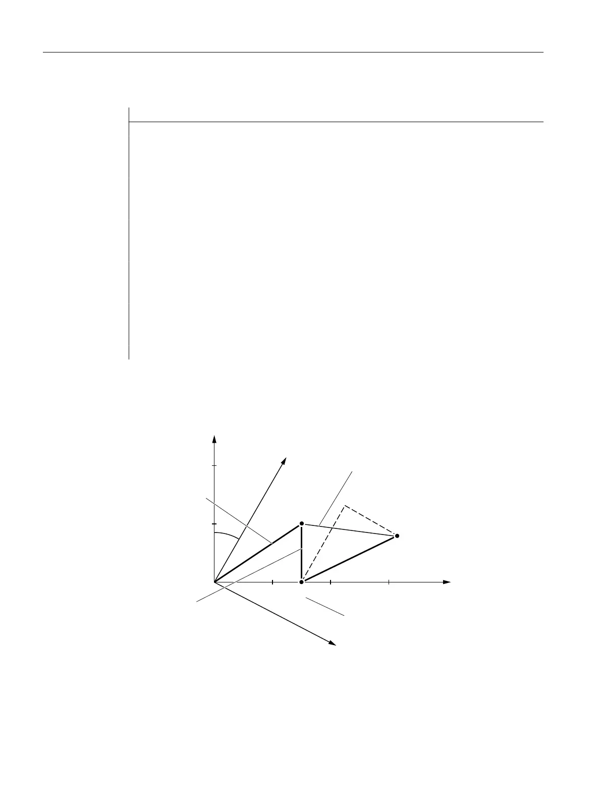
Setting data:SD42930 $SC_WEAR_SIGN is enabled in N90, i.e. the wear must be evaluated
with a negative sign. The compensation is vectorial (<CorComp> = 1), and the compensation
vector must be added to the wear (<CorMode> = 1). The geometrical relationships in the Z/X
plane are shown in the diagram below:
:HDU/ /
QHJDWLYHHYDOXDWLRQ
2ULJLQDOWRROOHQJWK
5HVXOWLQJZHDUFRPSRQHQW
*HRPHWU\
/ /
3
=
=
3
3
;
;
B&259$/< ; =
The geometry component of the tool remains unchanged due to <CorMode> = 1. The
compensation vector defined in the WCS (rotation around the y axis) must be included in the
wear component such that the total tool length in Fig. 3 refers to point P
2
. Therefore, the
resulting wear component of the tool is given by the distance of the two points P
1
and P
2
.
Work preparation
3.13 Tool offsets
NC programming
828 Programming Manual, 12/2019, 6FC5398-2EP40-0BA0
 Loading...


