M3: Direction of spindle rotation clockwise for master spindle
M<n>=3: Spindle direction of rotation clockwise for spindle <n>
M4: Direction of spindle rotation counter-clockwise for master spindle
M<n>=4: Spindle direction of rotation counter-clockwise for spindle <n>
M5: Spindle stop for master spindle
M<n>=5: Spindle stop for spindle <n>
SETMS(<n>): Set spindle <n> as master spindle
SETMS: If SETMS is programmed without a spindle name, the configured master spindle
is used instead.
Note
Up to three S-values can be programmed per NC block, e.g.:
S... S2=... S3=...
Note
SETMS must be in a separate block.
Example
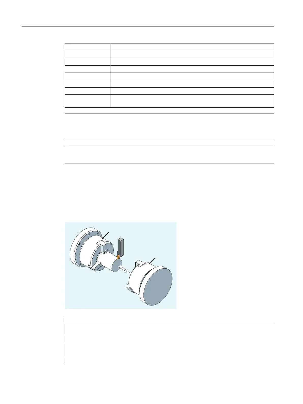
S1 is the master spindle, S2 is the second spindle. The part is to be machined from two sides.
To do this, it is necessary to divide the operations into steps. After the cut-off point, the
synchronizing device (S2) takes over machining of the workpiece after the cut off. To do this,
this spindle S2 is defined as the master spindle to which G95 then applies.
Program code Comment
N10 S300 M3 ; Speed and direction of rotation for drive spindle = pre-
set master spindle.
... ; Machining of the right-hand workpiece side.
N100 SETMS(2) ; S2 is now the master spindle.
N110 S400 G95 F… ; Speed for new master spindle.
... ; Machining of the left-hand workpiece side.
Fundamentals
2.6 Spindle motion
NC programming
90 Programming Manual, 12/2019, 6FC5398-2EP40-0BA0
 Loading...


