Programming and Operating Manual (Turning)
178 01/2017
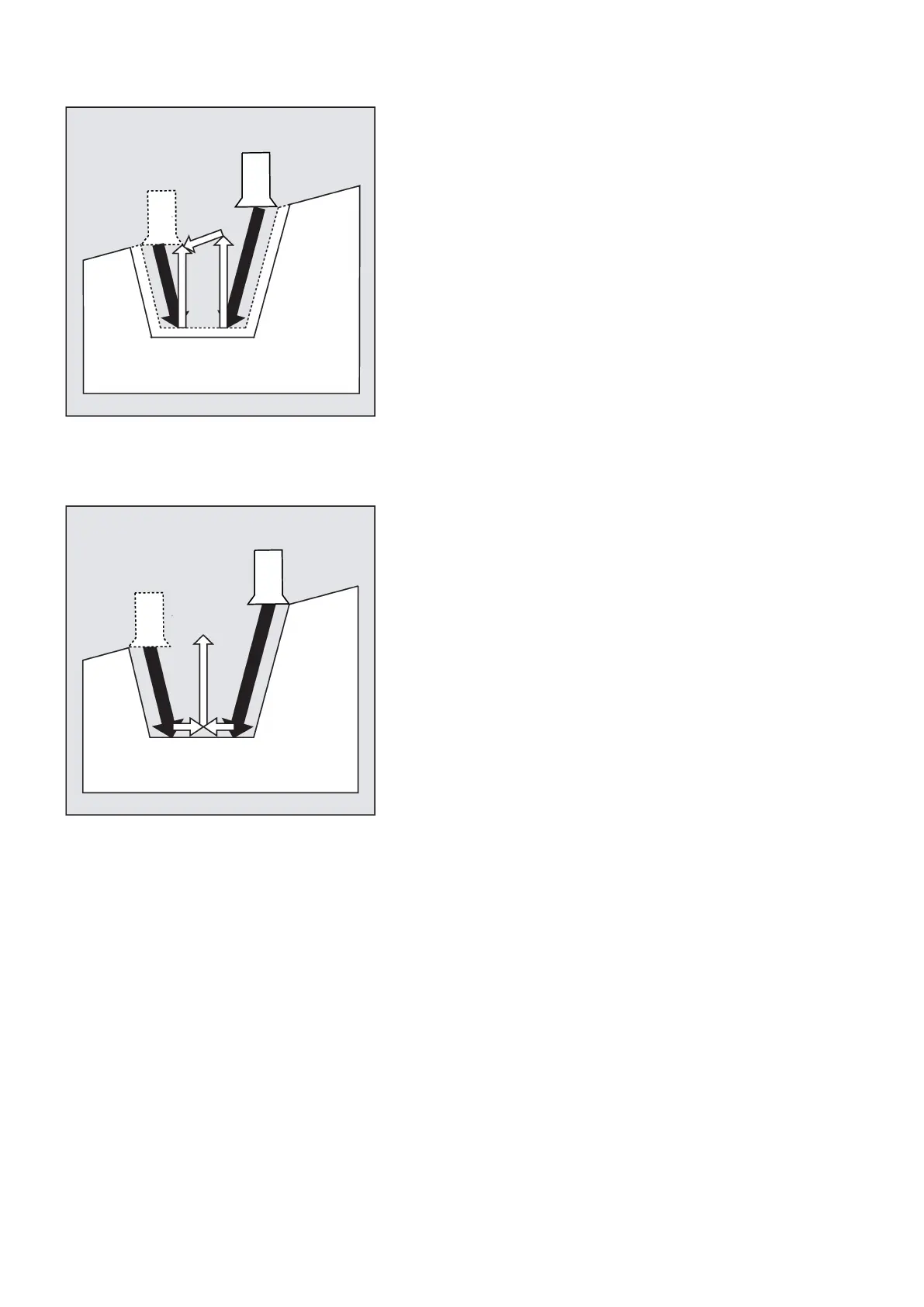
Stock removal of the finishing allowance parallel to the contour from the edge to the groove center. During this operation, the
tool radius compensation is selected and deselected by the cycle automatically.
Explanation of parameters
SPD and SPL (starting point)
These coordinates can be used to define the starting point of a groove starting from which the form is calculated in the cycle.
The cycle determines its own starting point. For an external groove, movement begins in the direction of the longitudinal
axis, for an internal groove in the direction of the facing axis.
Grooves at bent contour elements can be realized differently. Depending on the form and radius of the bend, either a
paraxial straight line can be laid over the maximum of the bend or a tangential oblique line can be created in a point of the
edge points of the groove.
Radii and chamfers at the groove edge make sense with bent contours only if the appropriate edge point is on the straight
line specified for the cycle.
See the following illustration for the parameters for CYCLE93: