Programming and Operating Manual (Turning)
01/2017
205
Explanation of the parameters
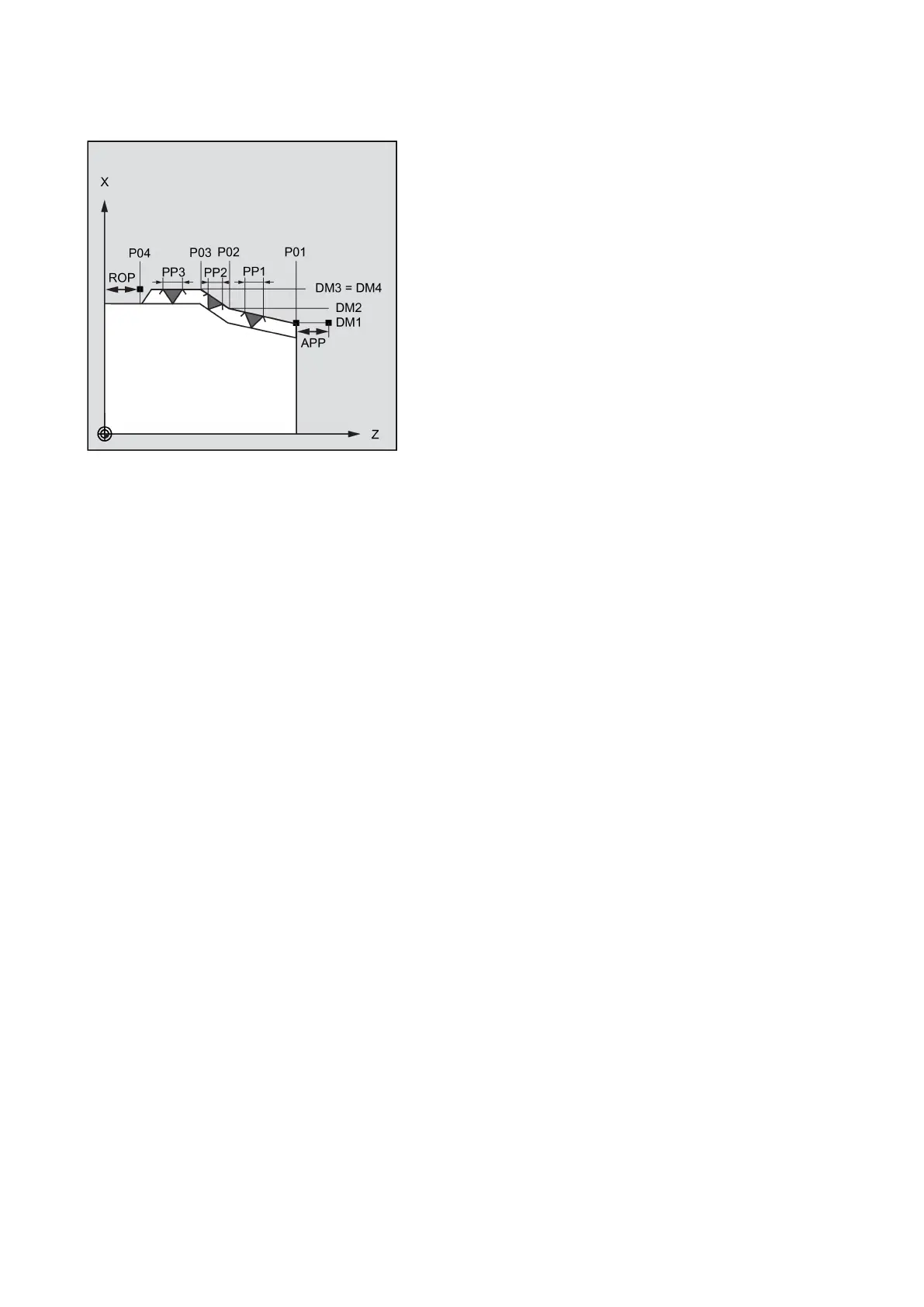
PO1 and DM1 (starting point and diameter)
These parameters are used to define the original starting point for the thread series. The starting point determined by the
cycle itself and approached at the beginning using G0 is located by the run-in path before the programmed starting point.
PO2, DM2 and PO3, DM3 (intermediate point and diameter)
These parameters are used to define two intermediate points in the thread.
PO4 and DM4 (end point and diameter)
The original end point of the thread is programmed under parameters PO4 and DM4.
With an inside thread, DM1...DM4 corresponds to the tap hole diameter.
Interrelation between APP and ROP (run-in/run-out paths)
The starting point used in the cycle, however, is the starting point brought forward by the run-in path APP, and,
correspondingly, the end point is the programmed end point brought back by the run-out path ROP.
In the transversal axis, the starting point defined by the cycle is always by 1 mm above the programmed thread diameter.
This lift-off plane is generated within the control system automatically.
Interrelation between TDEP, FAL, NRC and NID (thread depth, finishing allowance, number of roughing and idle passes)
The programmed finishing allowance acts paraxially and is subtracted from the specified thread depth TDEP; the remainder
is divided into roughing cuts. The cycle will calculate the individual infeed depth automatically, depending on the VARI
parameter. When the thread depth is divided into infeeds with constant cutting cross-section, the cutting resistance will
remain constant over all roughing cuts. In this case, the infeed will be performed using different values for the infeed depth.
A second version is the distribution of the whole thread depth to constant infeed depths. When doing so, the cutting cross-
section becomes larger from cut to cut, but with smaller values for the thread depth, this technology can result in better
cutting conditions.
The finishing allowance FAL is removed after roughing in one step. Then the idle passes programmed under parameter NID
are executed.