5 Operation
5.4 Configuration modes
Manual
168
SIPART DR21
C73000-B7476-C143-08
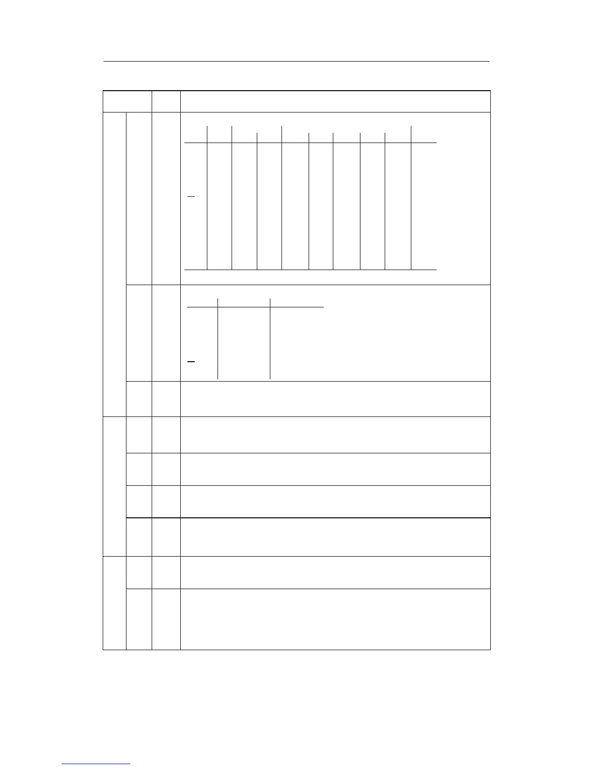
Structure
switch
switch
posi-
tion
Function
Assignment of the control signals to digital inputs
ital inputs
S23
S24
S25
S26
S27
S28
S29
S30
S31
S32
S33
S92
Stand. contr. Slot 3
Low DI1 DI2 DI3 DI4 DI5 DI6 DI7 High
CB01234567[8]
He[0]1234567--
N 0[1]234567--
Si 01[2]34567--
P[0]12345678
tS
[0]1234567--
+yBL[0]1234567--
--yBL[0]1234567--
bLb[0]1234567--
bLS[0]1234567--
bLPS[0]1234567--
tSH[0]1234567*)
* as of software version -B5
Dig
Direction of effect of the DIs on assigned control signals
S34
S35
S36
S37
S38
S39
S40
24 V = High 0 V = High
CB [0] 1
He [0] 1
N[0] 1
Si [0] 1
P[0] 1
tS
/tSH [0] 1
+/--yBL [0] 1
S41 Control signal CB
[0]
1
2
static without acknowledgement
static with acknowledgement
dynamic as pulse (flip- flop effect)
S42 Blocking of internal/external setpoint switching
[0]
1
2
internal only
external only
no blocking
S43 x tracking at H or N (DDC) or Si
S44 setpoint at CB failure
tpoi
1 safety setpoint SH
se
S45 T racking wi to the active setpoint w
or tracking of wvi to the active nominal ratio wv
[0] yes
1 no
S46 Direction of control action to xd ( w – x)
hm
1 reversed (Kp < 0)
gorit
3 z direction of control action against x
4 z direction of control action with x