3 Mounting and Commissioning
250
7UM61 Manual
C53000-G1176-C127-3
Table 3-12 Replacement modules for interfaces
The order numbers of the exchange modules can be found in the Appendix in Section
A.1.
Serial Interfaces
with Bus Capability
For bus-capable interfaces a termination is necessary at the bus for each last device,
i.e. termination resistors must be connected. In the case of the 7UM61, these are vari-
ants with RS485 or Profibus interfaces.
The terminating resistors are located on the RS485 or Profibus interface module,
which is on the B–CPU processor board ((1) in Figure 3-1 and 3-2), or directly on the
p.c.b. of the B_CPU processor PCB (see under margin heading "Processor module
B–CPU", Table 3-2).
Figure 3-7 shows the B–CPU PCB with location of the modules.
The module for the RS485 interface is shown in Figure 3-8, the module for the Profibus
interface in Figure 3-9.
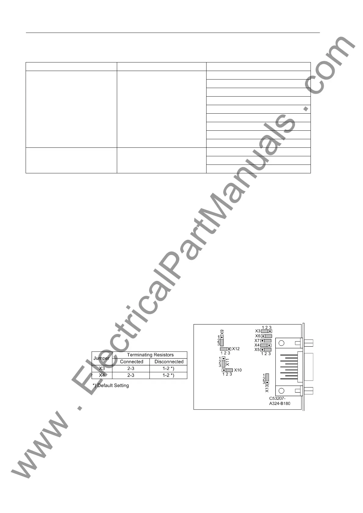
On delivery the jumpers are set so that the termination resistors are disconnected.
Both jumpers of a module must always be plugged in the same way.
Figure 3-8 Position of terminating resistors and the plug-in jumpers for configuration of the
RS485 interface
Interface Mounting Location / Port Replacement module
System interface B
RS232
RS 485
FO 820 nm
Profibus DP RS485
Profibus DP double ring
Modbus RS 485
Modbus 820 nm
DNP3.0, RS 485
DNP 3.0 820 nm
Service interface C
RS232
RS 485
FO 820 nm
www . ElectricalPartManuals . com

 Loading...


