3 Mounting and Commissioning
256
7UM61 Manual
C53000-G1176-C127-3
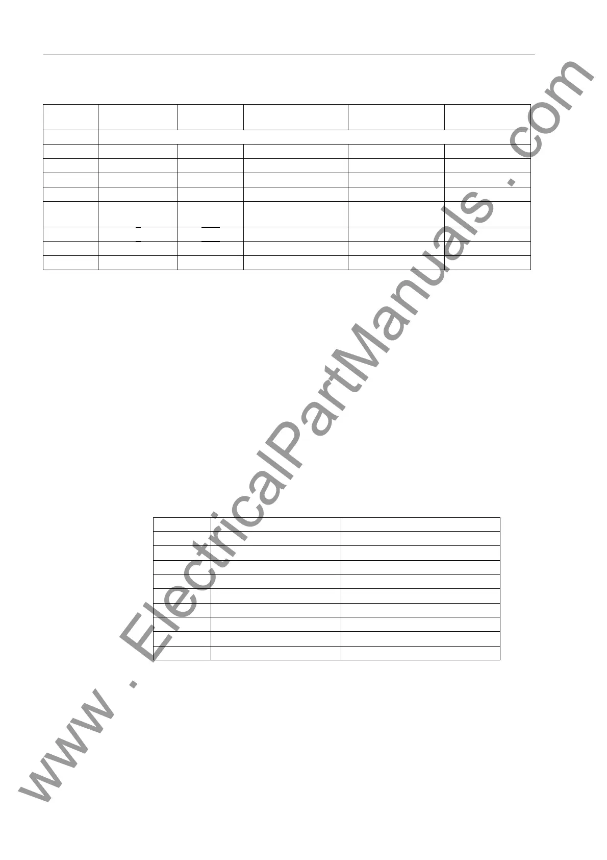
Table 3-14 DSUB socket connections for the various interfaces
1)
Pin 7 also can carry the RS232 RTS signal as an RS485 interface. Pin 7 may therefore not
be connected!
T e r m i n a t i o n The RS485 interface is capable of semi-duplex operation with signals A/A' and B/B'
with the common reference potential C/C' (GND). It is necessary to check that the ter-
mination resistors are connected to the bus only at the last unit, and not at other
devices on the bus. The jumpers for the terminating resistors are on the interface
module RS485 (Figure 3-8) or on the Profibus module RS485 (Figure 3-9). The termi-
nating resistors can also be connected externally (e.g. to the connection module). In
this case, the terminating resistors located on the module must be disconnected.
If the bus is extended, make sure again that only the last device on the bus has the
terminating resistors switched-in, and that all other devices on the bus do not.
Time Synchroniza-
t i o n I n t e r f a c e
It is optionally possible to process 5–V–, 12– V– or 24–V–time synchronization sig-
nals, provided that they are carried to the inputs named in the following table.
Table 3-15 D-SUB socket assignment of the time synchronization interface
1)
assigned, but not used
Connections for the time synchronization interface for panel surface-mounted devices
are described in the appendix.
Pin No. Operation inter-
face
RS232 RS 485 Profibus DP Slave,
RS 485
DNP3.0 Modbus,
RS485
1 Shield (with shield ends electrically connected)
2RxDRxD – – –
3 TxD TxD A/A' (RxD/TxD–N) B/B' (RxD/TxD–P) A
4 – – – CNTR–A (TTL) RTS (TTL level)
5 GND GND C/C' (GND) C/C' (GND) GND1
6 – – – +5 V (max. load 100
mA)
VCC1
7_
RTS –
1)
––
8_CTS B/B' (RxD/TxD–P) A/A' (RxD/TxD–N) B
9– – – – –
Pin No. Description Signal Meaning
1 P24_TSIG Input 24 V
2 P5_TSIG Input 5 V
3 M_TSIG Return Line
4–
1)
–
1)
5 SHIELD Shield Potential
6– –
7 P12_TSIG Input 12 V
8 P_TSYNC
1)
Input 24 V
1)
9 SHIELD Shield Potential
www . ElectricalPartManuals . com

 Loading...


