Actions up to serial number 1408 2 - 3
Siemens AG SPR2-230.814.01 Page 3 of 14 SIREMOBIL Iso-C 3D
Medical Solutions Rev. 05 08.04 CS PS 24
Drilling and threading holes for installing the limit switches at the
cable module 2
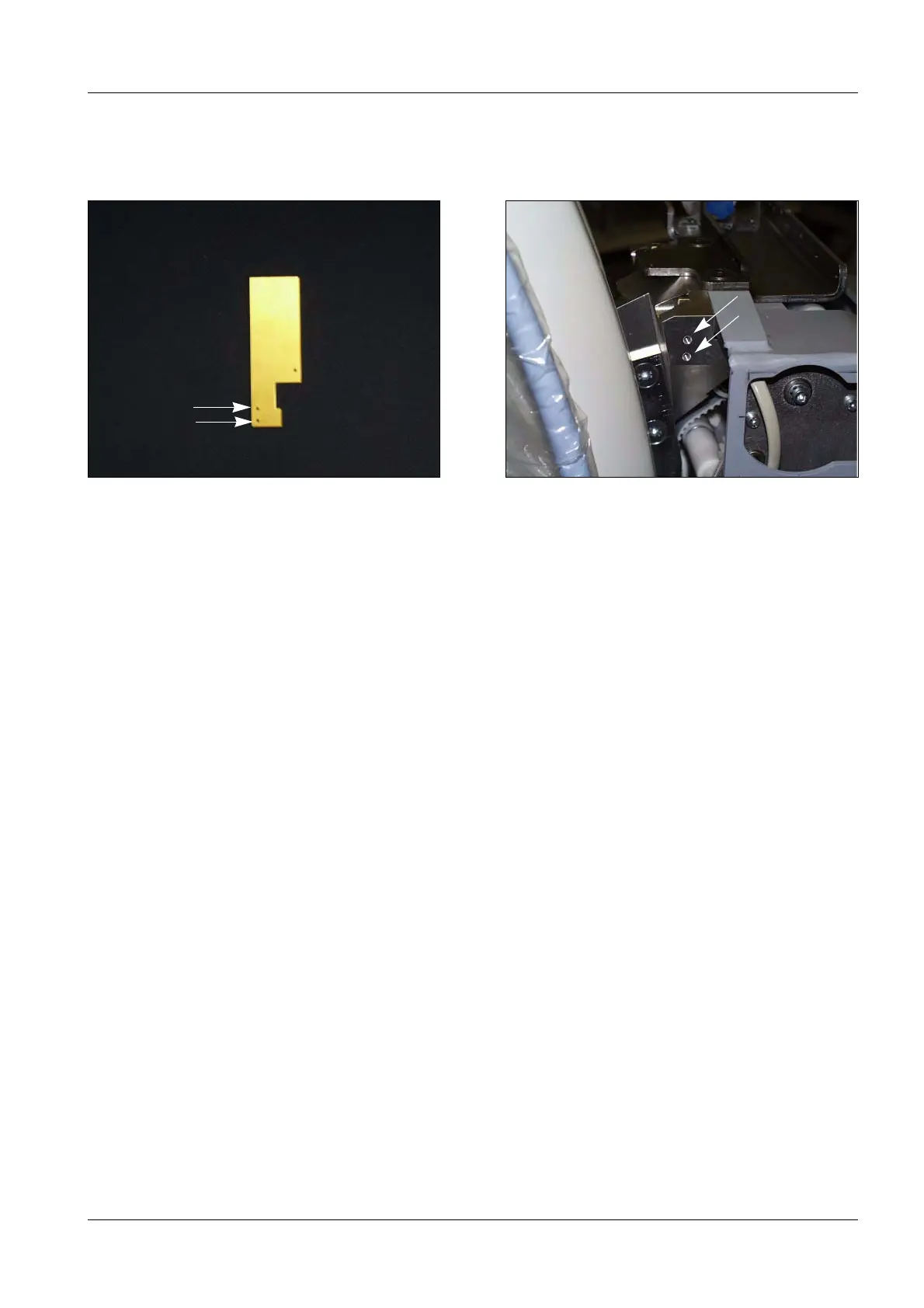
• Use the drilling template for the limit switch (Fig. 4).
• As seen from the operating console, two limit switches are installed to the left.
• Mark the location of the holes (Ê /Fig. 4 and Ê /Fig. 5).
• Punch-mark the markings and keep the shavings from dropping into the cable module.
• Continue to drill down to 15 mm using a 3.2 mm bit.
• Counterbore the holes.
• Cut the threads using an M4 thread tap (if required, use a drill with a left and right spiral
(clockwise and counterclockwise) or a tap wrench).
Fig. 4 Drilling template limit switch Fig. 5 Thread for limit switch

 Loading...


