3. Part of activities independent of serial number 6 - 23
Siemens AG SPR2-230.814.01 Page 23 of 42 SIREMOBIL Iso-C 3D
Medical Solutions Rev. 05 08.04 CS PS 24
Video switcher 6
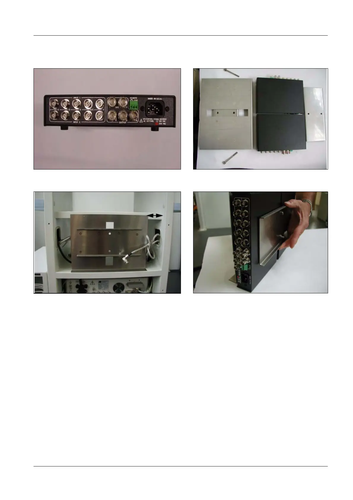
• Fig. 59 shows the Individual parts for the installation.
• Center the support plate for the video switcher on the back. It should be 60 mm away
from the edge (Fig. 60).
• Mark the holes.
• Remove the support plate.
• Punch-mark the holes.
• Drill the holes with a 2.7 mm drill bit.
• Install (Fig. 58) the two video switchers (Fig. 61). You won’t need the power cables
included in the package for the video switchers.
Fig. 59 Video switcher Fig. 60 Individual parts
Fig. 61 Support plate for video switcher in the monitor trolley Fig. 62 Video switcher installed
Markierung für Tastaturschublade
60mm

 Loading...


