SIREMOBIL Iso-C 3D SPR2-230.814.01 Page 32 of 42 Siemens AG
Rev. 05 08.04 CS PS 24 Medical Solutions
6 - 32 3. Part of activities independent of serial number
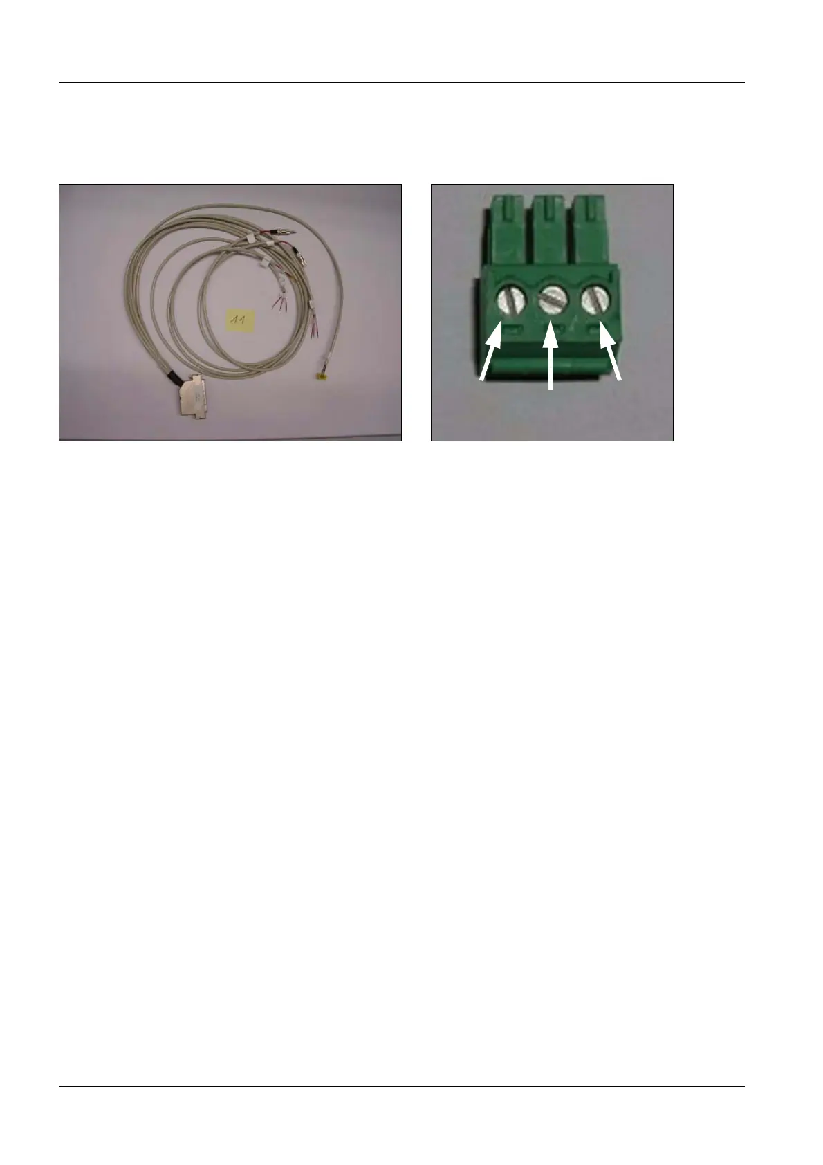
Cable no. 11, item number n.a., 6
is included in system cabling 71 39 855
• Connect plug 3D-PC I/O card (see Fig. 76) to the "Relay card" connector at the PC and
secure it with screws.
• Route the end VU1 to video switcher 1 (see Fig. 69), from the left side toward the top.
• Attach cable ends 1-3 to the Remote connector (Fig. 77),
1 to 1, 2 to 2, 3 to 3.
• Route the end VU2 to video switcher 2 (see Fig. 69), from the right side toward the top.
• Attach cable ends 1-3 to the Remote connector (Fig. 77),
1 to 1, 2 to 2, 3 to 3.
• Connect the plug to "Remote Status" on video switcher 2 (see Fig. 69).
• Connect the "PC out" plug to D210 X3.
Printer is available 6
• If a printer exists, disconnect the Remote plug at the printer and connect it with the
coupling of the Memoskop. Route the cable upward to the left.
• Connect the ’Printer Remote’ plug to the ’Remote’ printer connection.
No printer available 6
• If there is no printer, connect the ’Printer Remote’ plug with the Memoskop coupling. If
required, insulate the metal housing with tape.
• Plug D100.X1001 is not connected. Insulate the contacts, roll up the cable and attach it
using cable ties.
Fig. 77 Cable no. 11 Fig. 78 Video switcher, remote connector
123
connector 3D PC I/O

 Loading...


