Kapitelüberschrift hier eintragen 4 - 3
Siemens AG SPR2-230.814.01 Page 3 of 14 SIREMOBIL Iso-C 3D
Medical Solutions Rev. 05 08.04 CS PS 24
Limit switches 4
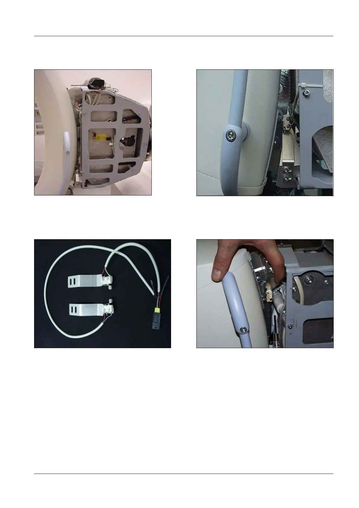
• Attach the two limit switches at the cable module using M4 x 8 screws, washers and
contact washers (Fig. 7, Fig. 8 and Fig. 9).
Setting the limit switches 4
• Move the C-arm by hand into the end position.
• Attach the two limit switches so that the cams enable the switching mechanisms at the
switches (Fig. 10).
• When set correctly, you can hear the click emitted by the limit switches.
• Angulation 0°.
• Test the function of the limit switches by moving the C-arm into the +95° und -95° orbital
positions.
• Check these settings at least twice.
Fig. 7 Attaching both limit switches Fig. 8 Limit switch in switching position
Fig. 9 Limit switch with cabling Fig. 10 Setting the limit switch

 Loading...


