SIREMOBIL Iso-C 3D SPR2-230.814.01 Page 2 of 14 Siemens AG
Rev. 05 08.04 CS PS 24 Medical Solutions
4 - 2 Kapitelüberschrift hier eintragen
• Move the C-arm into the 0º position (Fig. 1).
• Apply marks at 20 mm intervals to determine the lateral limit for the cam (Fig. 2).
• Position the cam. Ensure that the cam is flush with the top and mark the holes with the
cams laterally at the 20 mm mark (Fig. 3).
• Punch-mark the holes.
• Ensure that shavings or dust do not drop into the C-arm.
• Use a 3.2 mm bit for drilling. Continue until you have have drilled through the wall.
Ensure that you are not drilling beyond the wall (Fig. 4).
• Counterbore the holes.
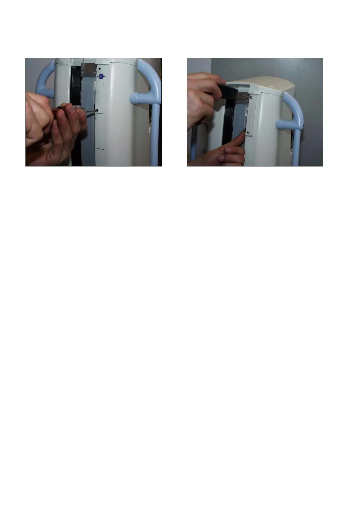
• Cut the threads using an M4 thread tap (e.g. use a tap wrench) (Fig. 5).
• Attach the cam using 2 countersunk screws M 4 x 8 (Fig. 6).
• Repeat these steps on the other side of the C-arm.
Fig. 5 Cutting the threads Fig. 6 Attaching the cam

 Loading...


