SIREMOBIL Iso-C 3D SPR2-230.814.01 Page 16 of 42 Siemens AG
Rev. 05 08.04 CS PS 24 Medical Solutions
6 - 16 3. Part of activities independent of serial number
Keyboard tray 6
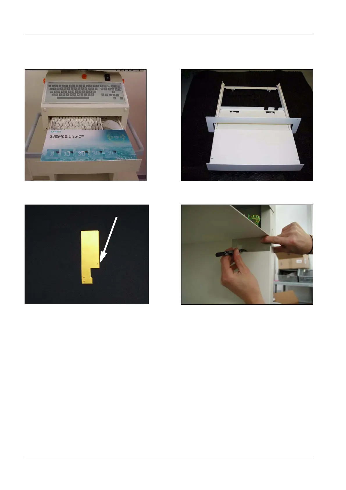
• Fig. 35 and Fig. 36 shows the keyboard tray after the installation.
• Mark the mounting hole at the back (on the left and on the right) using a drilling template
(Fig. 37 and Fig. 38).
• Draw the holes using the template. Ensure that the outer edge of the template lies flush
with the back.
• Punch-mark the holes.
• Drill the holes with a 2.7 mm drill bit.
Fig. 36 Fully installed keyboard tray Fig. 37 Keyboard tray
Fig. 38 Drilling template for keyboard tray Fig. 39 Mark hole at the back
marking for keyboard tray

 Loading...


