SIREMOBIL Iso-C 3D SPR2-230.814.01 Page 14 of 42 Siemens AG
Rev. 05 08.04 CS PS 24 Medical Solutions
6 - 14 3. Part of activities independent of serial number
PC support 6
Holes for PC support 6
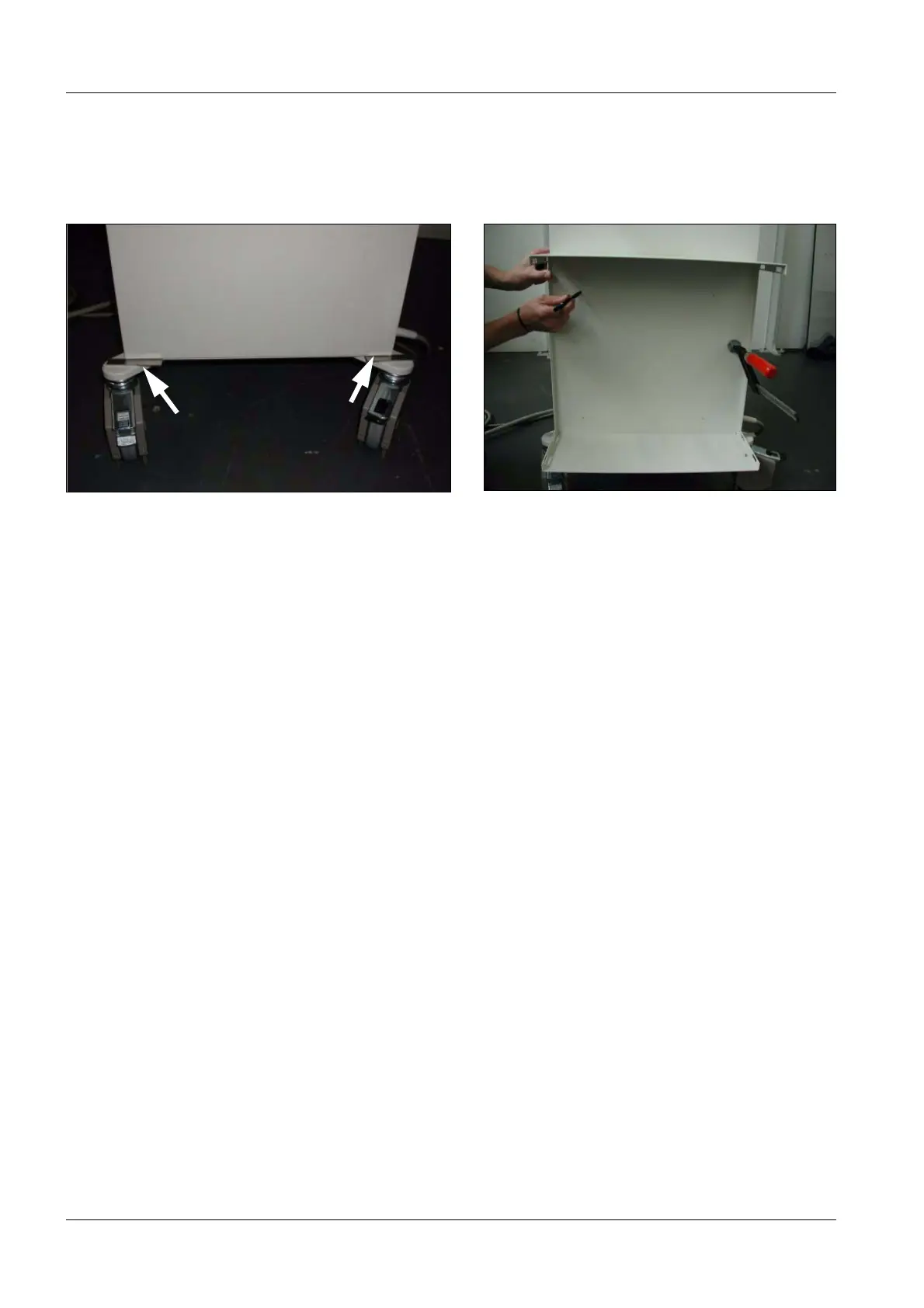
• Place the aluminium spacers (2) on the two rollers (Fig. 31).
• Disassemble the PC housing. You will still need the white foam rubber material.
• Position the PC housing on the spacer. The housing should be flush at the front. If so,
attach it with a screw clamp. The ground connection should point down toward the back
of the monitor trolley (Fig. 32).
• Mark the holes (Fig. 32).
• Remove the PC housing and spacers again.
• Punch-mark the holes.
• Start to drill the 4 holes at the marked locations using a 3.2 mm drill bit. Ensure that you
are not drilling into cables at the monitor trolley.
• Complete drilling the 4 holes by using a 6 mm drill bit.
• Deburr the holes.
• Remove the shavings. Use a vacuum cleaner, if needed.
Fig. 32 Spacers Fig. 33 PC housing

 Loading...


