3. Part of activities independent of serial number 6 - 13
Siemens AG SPR2-230.814.01 Page 13 of 42 SIREMOBIL Iso-C 3D
Medical Solutions Rev. 05 08.04 CS PS 24
Wiring of the displays
• Open the rear panel of both TFT displays above the connections.
• Route the power line cables and the video cables to the TFT displays.
• Live image TFT display (left display):
- Connect the video cable to the BNC socket VIDEO and lock it.
- Connect the shielding of the video cable to the ground of the monitor.
- Plug in the power line cable.
• Reference image and 3D TFT display (right display):
- Plug in the power line cable.
- Connect the 3-pin video cable to the BNC sockets and lock it:
Green cable - VIDEO
Blue cable - CS/HS
Red cable - VS
• Close both panels again which are located above the display connections.
• If required, retract the power line cables and video cables into the monitor trolley.
- Route the cables without sharp bending radius.
- It is recommended to ensure that the cables are covered by both support arm rails in
the area between support arm base and the displays (see Fig. 27).
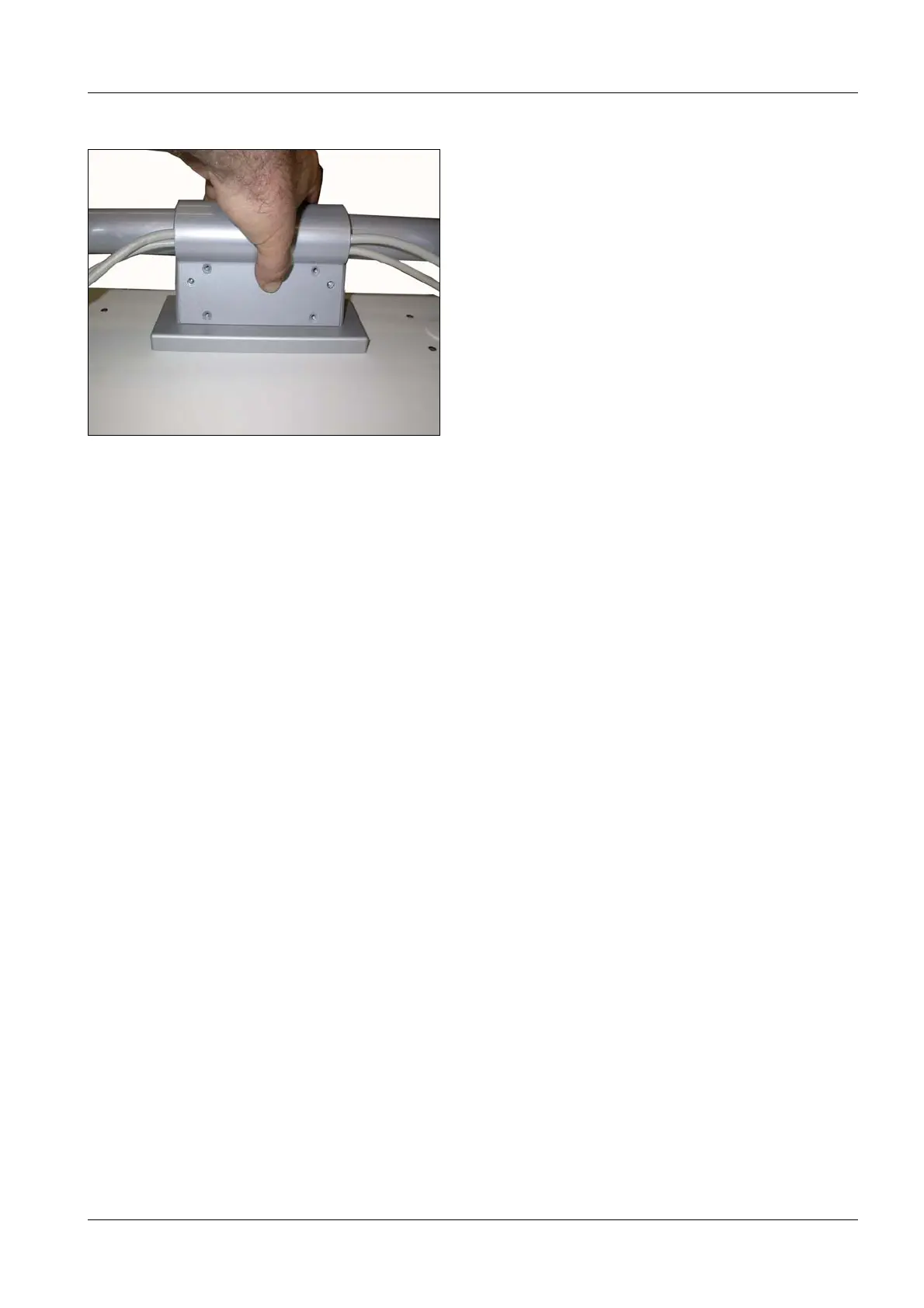
- The cables should rest in the cable bushes of the support arm base without excessive
pulling force or stress (Fig. 31).
• Reattach the cover of the support arm (Fig. 31).
• When present, switch on the power switches of the TFT displays.
Fig. 31 Cover of the support arm
Mark for the keyboard tray

 Loading...


