2. Part of activities independent of serial number 5 - 3
Siemens AG SPR2-230.814.01 Page 3 of 8 SIREMOBIL Iso-C 3D
Medical Solutions Rev. 05 08.04 CS PS 24
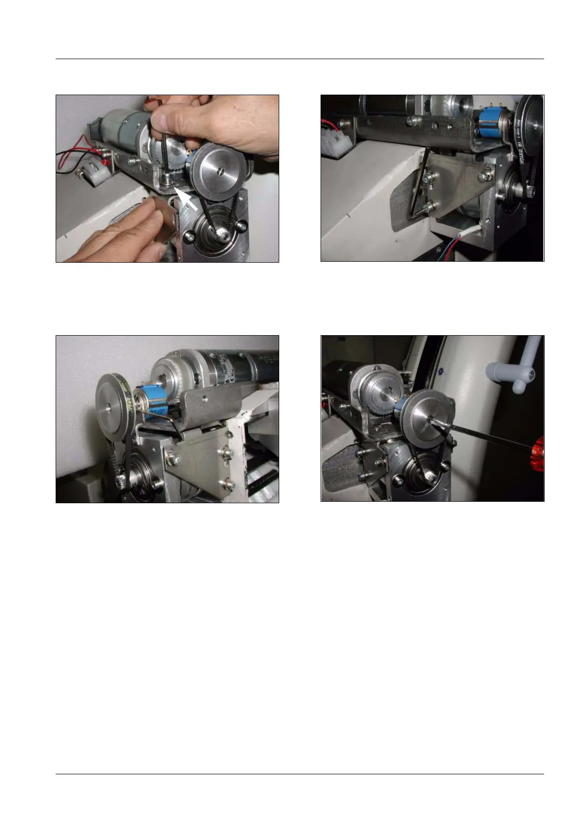
• Attach lateral brackets (Fig. 8) on both sides (Fig. 9), first on top and then on the side.
• Move the C-arm into the -95° degree orbital position (limit switch = side of image
intensifier).
• Loosen the Allen screw at the belt pulley (Fig. 10).
• Attach the outside toothed belt (see Fig. 10).
• Turn the potentiometer counterclockwise into the end position using a screwdriver
(Fig. 11).
• Once the potentiometer is in this position, turn it fully clockwise twice.
• Secure the belt pulley with the Allen screw (Fig. 10).
Fig. 8 Lateral bracket Fig. 9 Lateral bracket
Fig. 10 Belt pulley Fig. 11 Potentiometer
top

 Loading...


