Communication via CAN bus (CANopen)
AP10
Date: 28.02.2022 Art. No. 86853 Mod. status 37/22 Page 17 of 78
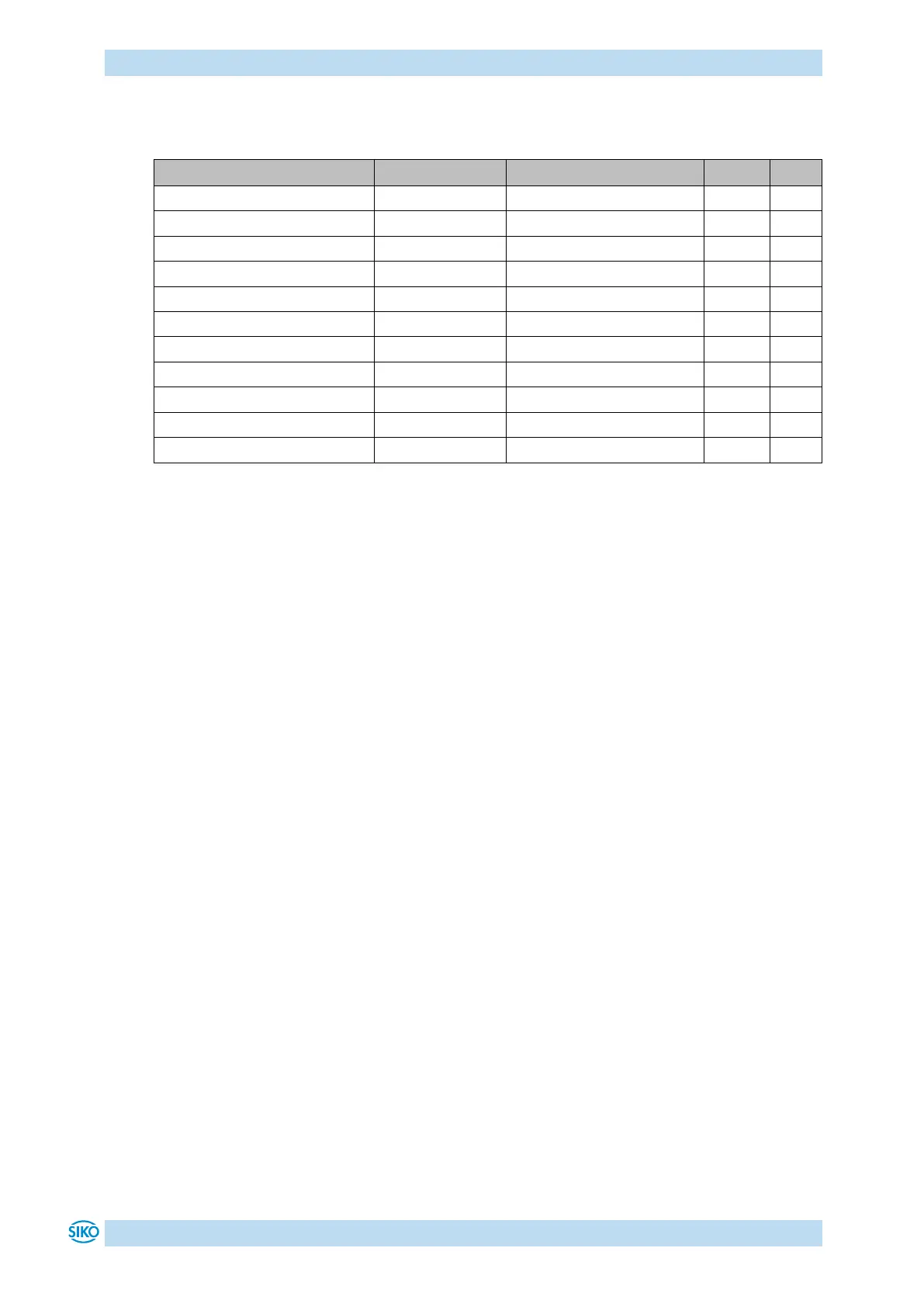
The following function codes have been defined in the "Pre-defined Connection Set" (only the
function codes used in the present device are listed):
Table 10: Overview of COB identifiers
Changes to COB-IDs are only possible in the PRE-OPERATIONAL NMT status. First, the COB-ID
must be deactivated via Bit 31 = 1b before it can be changed and reactivated.
The COB-ID of the SYNC object is an exception. There, Bit 30 must be = 0 to enable the
change of the COB-ID. The COB-ID could be changed any time because Bit 30 cannot be set to
1 in the AP10 device.
The identifier determines the priority of the message. The lower the value of the identifier,
the higher the priority of the message.
The node number (Node-ID) (see object 5F0Ah: Node-ID, Auto-ID and Baud rate Bus CAN) is
assigned in every bus system once while AP10 is being configured. Node-ID = 0 is reserved
and must not be used; thus, the node numbers are in the range of 1 to 127.
A newly set node number will only be adopted with reinitialization (see chapter 5.2.1).
The set point display is delivered with the factory-set Node-ID 125 (7Dh).
Control field:
Contains bit-by-bit information on the number of user data and decides whether a data frame
or a Remote Transmission Request (RTR) frame is concerned.
Data field:
Contains up to 8 bytes of user data. The user data has a different meaning depending on the
channel selection.
CRC:
Contains bits for error detection.
ACK/EOF:
The ACK/EOF field contains telegram acknowledgement bits as well as bits for determining the
end of telegram.