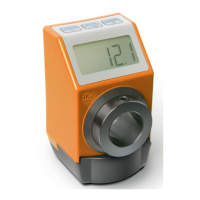
With supply voltage applied to the position indicator with factory settings, the actual value
will be displayed in the 1
st
row and the set point in the 2
nd
row. If there is no valid set point,
"---" will be displayed in the 2
nd
row. The values displayed are determined by the operating
mode.
Direction indicators (arrows) support positioning.
The battery symbol is shown with a critical or insufficient battery status.
With incremental measurement function activated, the incremental measurement symbol
is shown.
If battery voltage drops to a critical value, the battery symbol on the display will flash. If it
falls below the minimum value, the symbol will glow permanently.
3.2.1 Extended display range
Values up to -999999 can be displayed by means of the control word. If the relevant bit has
been set and the value to be displayed is between -199999 and -999999, then the negative
sign and the digit of the highest order will flash alternately. If the value range drops below -
99999, "" will be displayed.
This function is not available in the alpha-numeric display mode for unacknowledged values.
3.3 LED display
In its basic state (factory setting) the LED display has different meanings depending on the
operating mode (see chapter 4.1.1 and 4.1.2).
With the basic function of the LEDs inactivated, every LED can be controlled independently via
the control word (see object 5F12h: Display orientation and LEDs and chapter 5.3.2).
3.4 Keys
Pressing the key enables or disables the incremental measurement function. With the
Auto-ID function, the new ID is adopted by actuating this key (see chapter 5.6).
Pressing the key starts calibration (see chapter 4.5.1) and acknowledges a pending error
(see chapter 4.4.2).
Pressing the key starts the parameterization mode (see chapter 4.3).
In the "Alpha-numeric display" operating mode, the set points previously received (set point1
and set point2) are acknowledged via the respective buttons depending on the
acknowledgment settings (see chapter 5.7.2.45).