EasyManuals Logo

Sinee EA180 Series Manual

Sinee EA180 Series
109 pages
To Next Page IconTo Next Page
To Previous Page IconTo Previous Page
Page #15 background imageLoading...
Page #15 background image
EA180 Servo Drive Manual
15
Signal
Pin #
Description
SIGN-
32
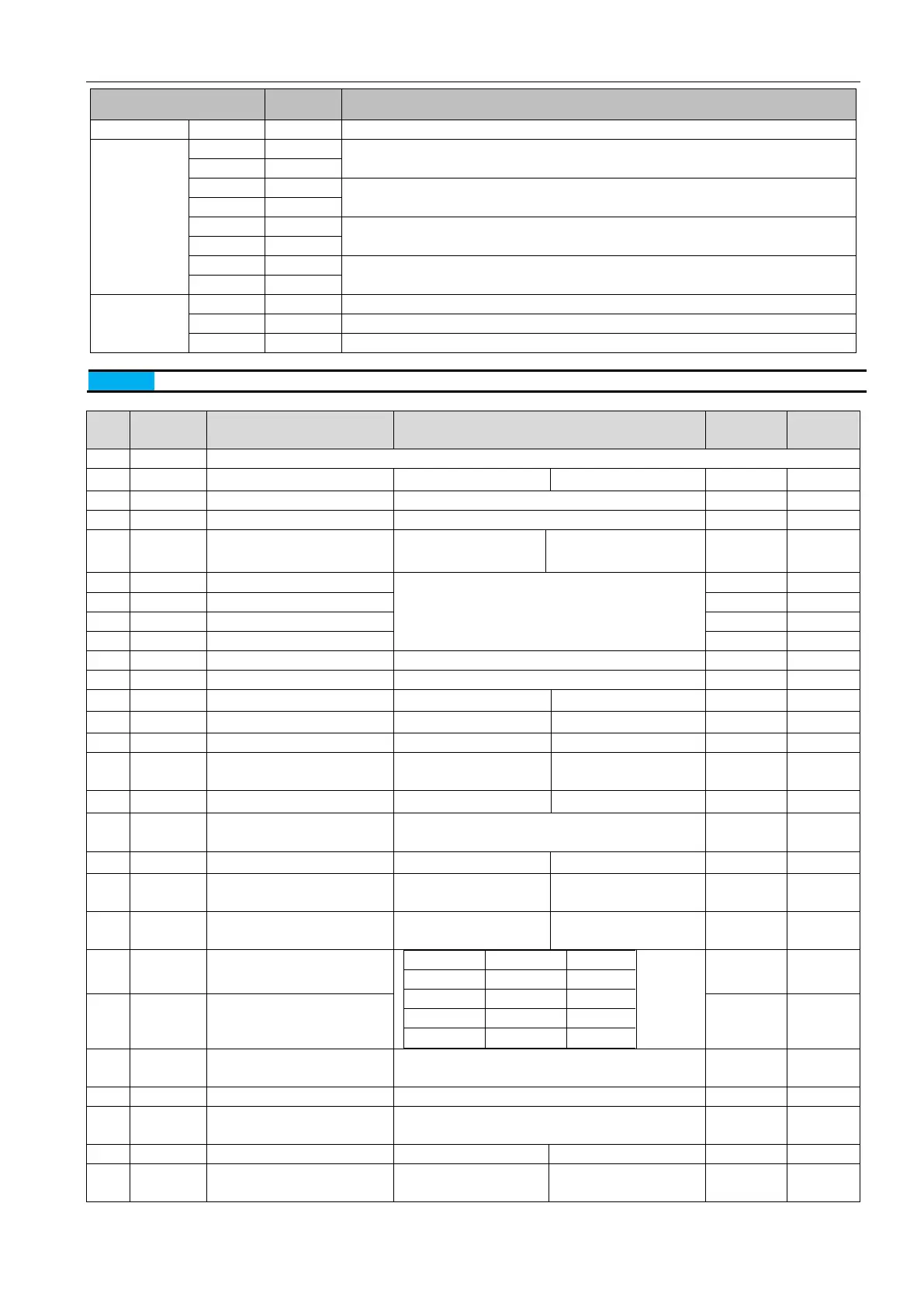
Position direction instruction -
Freq. diverting
output
PA+
28
A pulse differential frequency division output, maximum allowable current 20mA
PA-
13
PB+
12
B pulse differential frequency division output, maximum allowable current 20mA
PB-
27
PZ+
11
B pulse differential frequency division output, maximum allowable current 20mA
PZ-
26
OCZ
35
Z pulse open collector output with maximum permissible current 40mA.
GND
14
Analog input
AI1
15
Analog input 1
AI2
30
Analog input 2
GND
29
Analog input signal ground
Note
All GND terminals are connected within the drive, and all COM terminals are connected within the drive
3.4.3 DIDigial Input function
Value
Name
Function
Description
Triggering
mode
Running
mode
0
Disabled
Terminal invalid
1
S-ON
Servo enabled
ONenabled
OFFdisenabled
Level
P S T
2
ALM-RST
Alarm and fault reset
OFF→ONresettable fault reset
Edge
P S T
3
P-CLR
Position error clear
Edge/Level
P
4
DIR-SEL
Speed direction selection
ONnegative speed
command direction
OFF the setting speed
direction
Level
S
5
CMD0
Internal command bit0
In the multi preset position control mode, the signal is
multi position switching function;
In the multi preset speed control mode, the signal is a
multi speed switching function;
Level
P S
6
CMD1
Internal command bit1
Level
P S
7
CMD2
Internal command bit2
Level
P S
8
CMD3
Internal command bit3
Level
P S
9
CTRG
Internal command trigger
multiple position trigger
Edge
P
10
MSEL
Control mode switched
Level
P S T
11
ZCLAMP
zero speed clamp enabled
ONenabled
OFFdisenabled
Level
S
12
INHIBIT
Pulse inhibit
ON-inhibt
OFFpulse input allowed
Level
P
13
P-OT
inhibit positive drive
ON-inhibit
OFF-allowed
Level
P S T
14
N-OT
Inhibit negative drive
ON-inhibit negative drive
OFF-allowed negative
drive
Level
P S T
15
GAIN_SEL
Gain switched
ONuse second gain
OFFuse first gain
Level
P S T
16
J_SEL
Inertia switched
ONuse second inertia ratio P4-11
OFFuse first inertia ratioP4-10
Level
P S T
17
JOG_P
Positive jog
ONpostive jog
OFFno function
Level
S
18
JOG_N
Negative jog
ONnegative inching
operation
OFFno function
Level
S
19
TDIR-SEL
Torque command direction
selection
ON negative torque
command
OFFthe setting torque
direction
Level
T
20
GNUM0
Electronic gear ratio numerator
selection 0
GNUM1
GNUM0
Code
0
0
P1-04
0
1
P1-08
1
0
P1-10
1
1
P1-12
Level
P
21
GNUM1
Electronic gear ratio numerator
selection 1
Level
P
22
ORGP
External detector input
Rising edge: external detector is valid
Falling edge: external detector is invalid
Edge
P S T
23
SHOM
Homing
OFF→ON: Homing starts
Edge
P S T
24
TL2
External torque limiting
ON- External torque limiting enable
OFF- External torque limiting is prohibited
Level
P S T
25
EMGS
Emergency stop
ONemergency stop
OFFno function
Level
P S T
33
TDIR-SEL
Position command direction
selection
ON: negative position
command direction
OFF: the setting command
direction
Level
P

Table of Contents

Other manuals for Sinee EA180 Series

Questions and Answers:

Question and Answer IconNeed help?

Do you have a question about the Sinee EA180 Series and is the answer not in the manual?

Sinee EA180 Series Specifications

General IconGeneral
BrandSinee
ModelEA180 Series
CategoryServo Drives
LanguageEnglish

Related product manuals