8
23
37
38
9
24
39
10
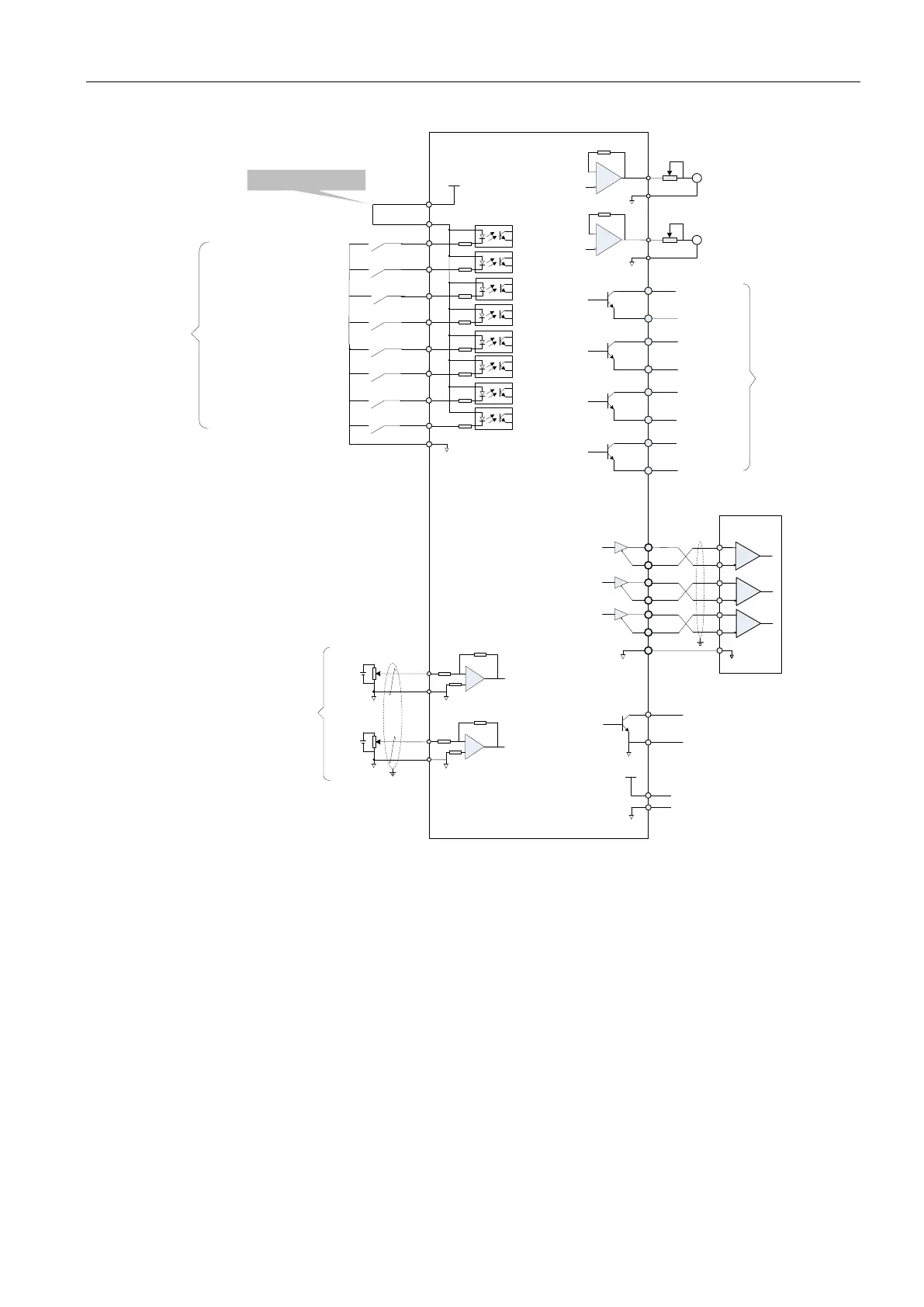
DO1
DO1-
DO2
DO2-
DO3
DO3-
DO4
DO4-
State output
Encoder frequency division
pulse output-differential
PE
PA+
PA-
PB+
PB-
PZ+
PZ-
28
13
12
27
26
GND
29
11
35
14
Upper
computer
GND
Encoder z-phase Open
collector output
GND
OCZ
+5V
+5V
GND
6
29
GND
AO1
Analog 1
output
Analog 2
output
15
29
30
29
GND
GND
AI2
AI1
EA180
Servo Drive
Servo ready
Brake
output
Speed
comparison
Fault output
PE
Internal +5V power with
maximum permissible
current 200mA
+24V
+24V pulse
25
COM+
21
DI1
5
DI2
20
4
DI3
19
3
18
2
DI4
DI5
DI6
DI7
17
DI8
ALM-RST
N-OT
CMD0
CMD1
CMD2
CMD3
S-ON
P-OT
COM
State input
Internal 24V supply
7
Servo enabled
Alarm reset clear
No positive drive
No negative drive
Speed internal command bit0
Speed internal command bit1
Speed internal command bit2
Speed internal command bit3
S-RDY
BK
V-CMP
ALM
A
GND
AO1
A
Speed command
Analog speed given
Signal input: + 10V
Input impedance is about 9K ohms
Analog torque limiting
Signal input: + 10V
Input impedance is about 9K ohms
 Loading...
