EA180 Servo Drive Manual
24
3.6 CN1 analog monitoring output terminal
CN1 terminal has two shapes, the pin description is as follows:
Table 3-11 analog output
Analog output 1, output voltage
-10V~10V ,max.output current 1mA
can set by P6
group codes
Servo drive
AO1
GND
1
2
AO2
3
A
A
Analog ouput 2, output voltage
-10V~10V ,max.output current 1mA
analog signal common ground
not connect with any signal cable
Notes:
1) After control power is OFF, the analog monitoring output terminal may output 5V during the longest 10ms period.
2) The analog terminal has a maximum output current of 1mA, exceeding this value may lead to the damage to the drive. Please
consider this fully when selecting the load.
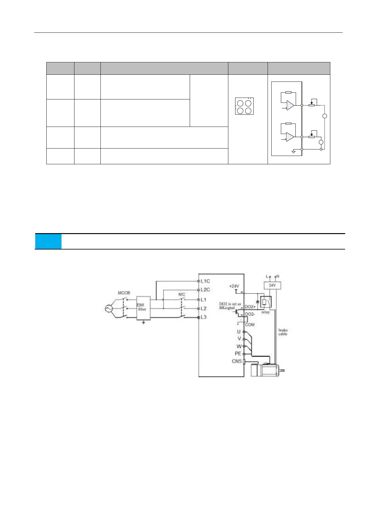
3.7 Brake
When the motor is applied to the vertical shaft or the like, to prevent the movement due to the gravitiy or external force when power
failure, need to choose the servo motor with brake.
1. The brake is used to keep the stop state of the servo motor, not used to stop motor from running.
2. The brake may give off clicking sound when the motor runs, but it does not affect its function.
The brake should be supplied by the external 24VDC, here below is the wiring method of brake signal and power.
Figure 3-20 Brake signal and power cable
3.7.2 Brake cable notes:
1) The intermediate relay should be controlled by the terminal defined as 2 function (BK) signal terminals (pictured above is
DO2+, DO2-), and switch on/off the brake power by the NO contact of the intermediate relay.
2) Be sure to use external power supply for the brake. The 24V DC supply for the intermediate relay coil can be applied from
the servo drive itself, does not propose to share the same power with the brake when using an external power supply.
3) In the use of external power supply for relay coil, please note that the DO2+ terminal should be connected to the positive
terminal, DO2- terminal connected to the negative terminal of the supply.
4) The brake operation voltage is at least 21.5V, so it is necessary to take full account of the pressure drop caused by the wire
resistance to maintain the power supply of the brake. It is recommended that more than 0.5
cables be used.
5) It is better not to share the power with other electrical appliances to prevent the brake from malfunction due to the reduction
of voltage or current by other electrical appliances.
 Loading...
