EA180 Servo Drive Manual
68
Parameter function: setting the function of DI1~DI8 terminal, see Table 5-5. 8 DI corresponding function settings, you can set the
range of 0~99, but the current part is reserved.
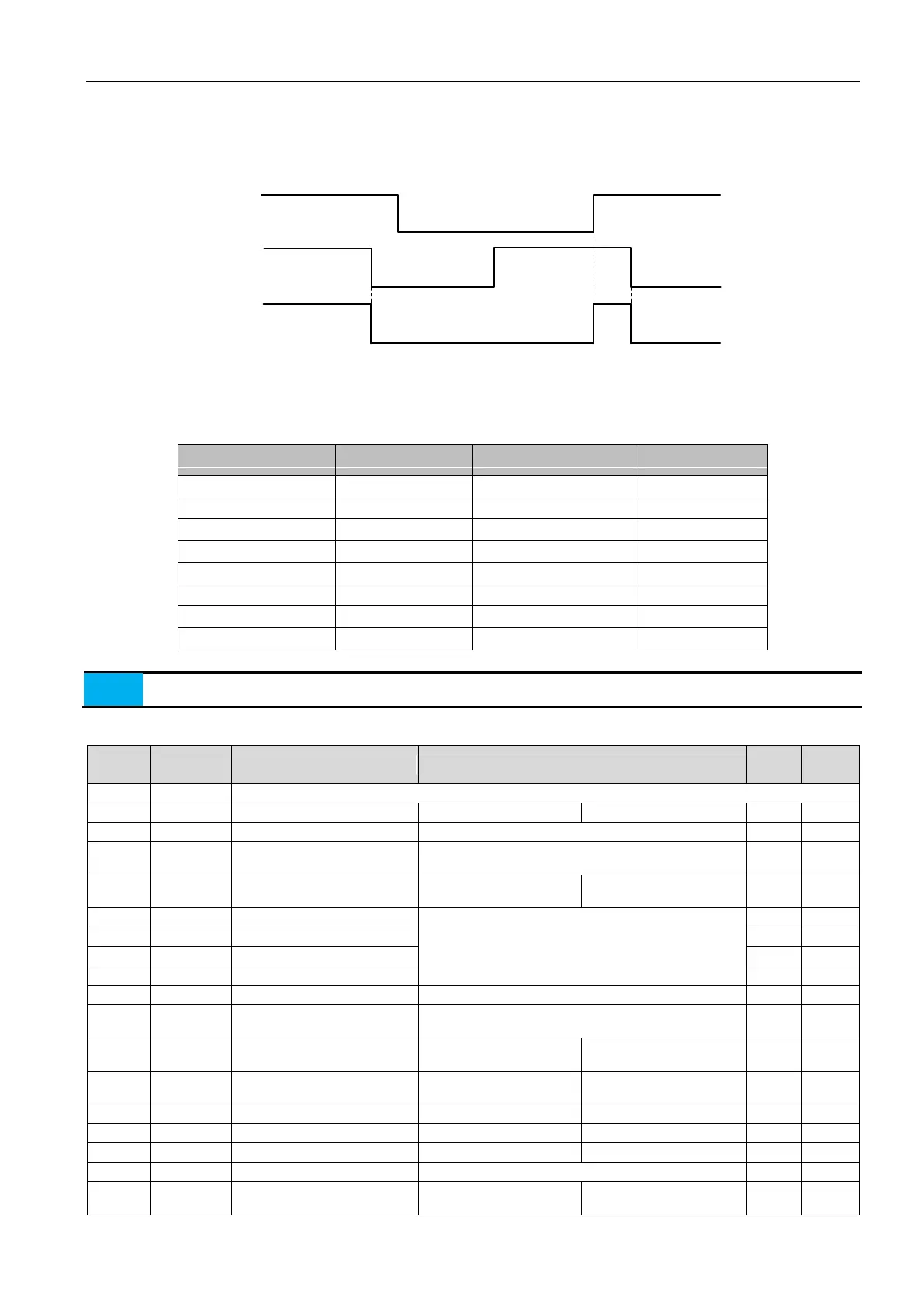
Different DI can set the same function number, the corresponding logical relationship is OR, e.g. when the D1 or D2 is valid,
the corresponding function will happen. For example, P6-02=1, P6-03=1, when one of DI1 and DI2 is valid, servo ON; when two
are invalid, servo OFF.
DI1
DI2
/S-ON
Terminal void
Command active
Terminal active
Terminal active
Terminal void
Terminal void
Terminal void
Terminal active
Command voidCommand void
Command active
*:When the servo drive is first set to a different operating mode, i.e., when the P0-00 parameter setting value changes, the initial
value of the DI terminal selection parameter changes.
The following table shows the default terminal function for different P0-00 setting:
When the servo drive is set to a mixed operation mode, i.e., the P0-00 parameters are 3, 5, 6, 7, 8, and even the initial setting,
the setting function of the DI terminal is not changed.
Table 5-5 digital input (DI) function definition table
OFF: Servo enable canceled
Position deviation counter
cleared
See the definition of trigger P1-16
Speed command direction
selection
ON: Reverse speed
command
When multi-position control mode, the signal is a
multi-position switching function;
When the multi-speed control mode, the signal is a
multi-speed switching function;
Control mode switching, meaning of ON / OFF refers to
description of P0-00
Speed command zero fixed
enable
ON: Zero fixing function is
enabled
ON-Prohibit command
pulse input
ON-Prohibit forward drive
ON- prohibit reverse drive
OFF: using the first gain
ON: The second inertia ratio P4-11
OFF: using a first inertia
ratio P4-10
 Loading...
