EA180 Servo Drive Manual
75
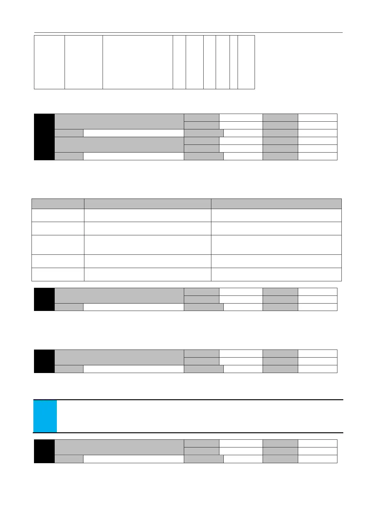
the high and
low bit setting
of 32-bit
function code
1:Read: high 16-bit first,then
low 16-bit
2:Read: low 16-bit first, then
high 16-bit; Write: on the
contrary
3:Read: high 16-bit first, then
low 16-bit; Write: on the
contrary
6.12 P8-xx Extended function parameters
Parameter function:
Set the motor speed and acceleration and deceleration time of the JOG, the acceleration and deceleration time reference is the
motor speed time from 0 to the rated speed or vice versa. The drive can carry out inching through the function parameter AF-02 when
the servo is enabled OFF, or by the DI terminal set to JOG-P and JOG-N when the servo is enabled ON or OFF.
Jogging command execution:
JOG terminal OFF→ON and on
The speed at which to run from P8-01 to P8-00, and
continuously running
Slow down to zero speed at the speed of P8-01, restore
to original control mode
Position mode of
pulse command
Clear droop pulses, starting at the current speed, run
from P8-01 to P8-00, and run continuously.
Resume position mode the moment when JOG
command inactive, start receiving the command pulse.
Multi-stage position
mode
Clear droop pulses, starting at the current speed, run
from P8-01 to P8-00, and run continuously.
Restore the multi-stage position mode, run the
remaining pulse command, (the cleared stranded pulse
is no longer executed)
The speed at which to run from P8-01 to P8-00, and
continuously running
Accelerate by P2-04 or decelerate by P2-05 to the
specific speed of current speed command.
Starting from current speed, run from P8-01 to P8-00,
and continuously running.
Resume torque mode, and run according to the current
torque command
Auto tuning torque identified by offline inertia
Parameter function:
When the load inertia ratio is offline, the percentage of the torque relative to the motor's rated torque is the output torque of the
motor.
The greater the setpoint, the greater the possible mechanical impact, but the shorter the identification time and the number of
turns required by the motor, please set the appropriate value according to the machine.
The maximum number of turns identified by offline
inertia
Parameter function:Sets the maximum number of cycles allowed for off-line inertia identification
If the motor runs in this loop, the system inertia is not recognized successfully, or, in the course of inertia identification, the motor
cannot run to this circle, then Al028 alarm occurs.
When the system inertia can not be recognized, and the mechanical condition allows the motor to rotate more turns, please
increase the set value of this parameter.
When the system inertia can not be recognized, and the mechanical condition does not allow the motor to rotate more turns,
please add the set value of P8-02.
See section 6.6 for reference.
Absolute encoder maximum number of revolutions
Parameter Function: Set the upper limit of the turns of absolute encoder
If the number of revolutions of the absolute encoder is positive and its value exceeds the set value and the current command
direction is positive, the forward overtravel is processed. LED display p-ot, WARN terminal output is valid; if the number of
 Loading...
