EA180 Servo Drive Manual
26
Motor power
Brake command
Motor speed
Power on
P0-10
Disengaged
Engaged
ON
OFF
Power off
Servo enable(/S-ON)
Or alarm or power OFF
Coast to stop
P0-09
Figure 3-23 Brake actions when the servo motor is rotating
1. Even if the value set in the P1-10 is more than the highest speed of the servo motor, it will be limited to the
maximum speed of the servo motor.
2. Do not assign the motor rotation signal (TGON) and the brake signal (BK) to the same terminal. If assigned to
the same terminal, due to the vertical axis of the falling speed, will make the TGON signal ON, the brake may not
move.
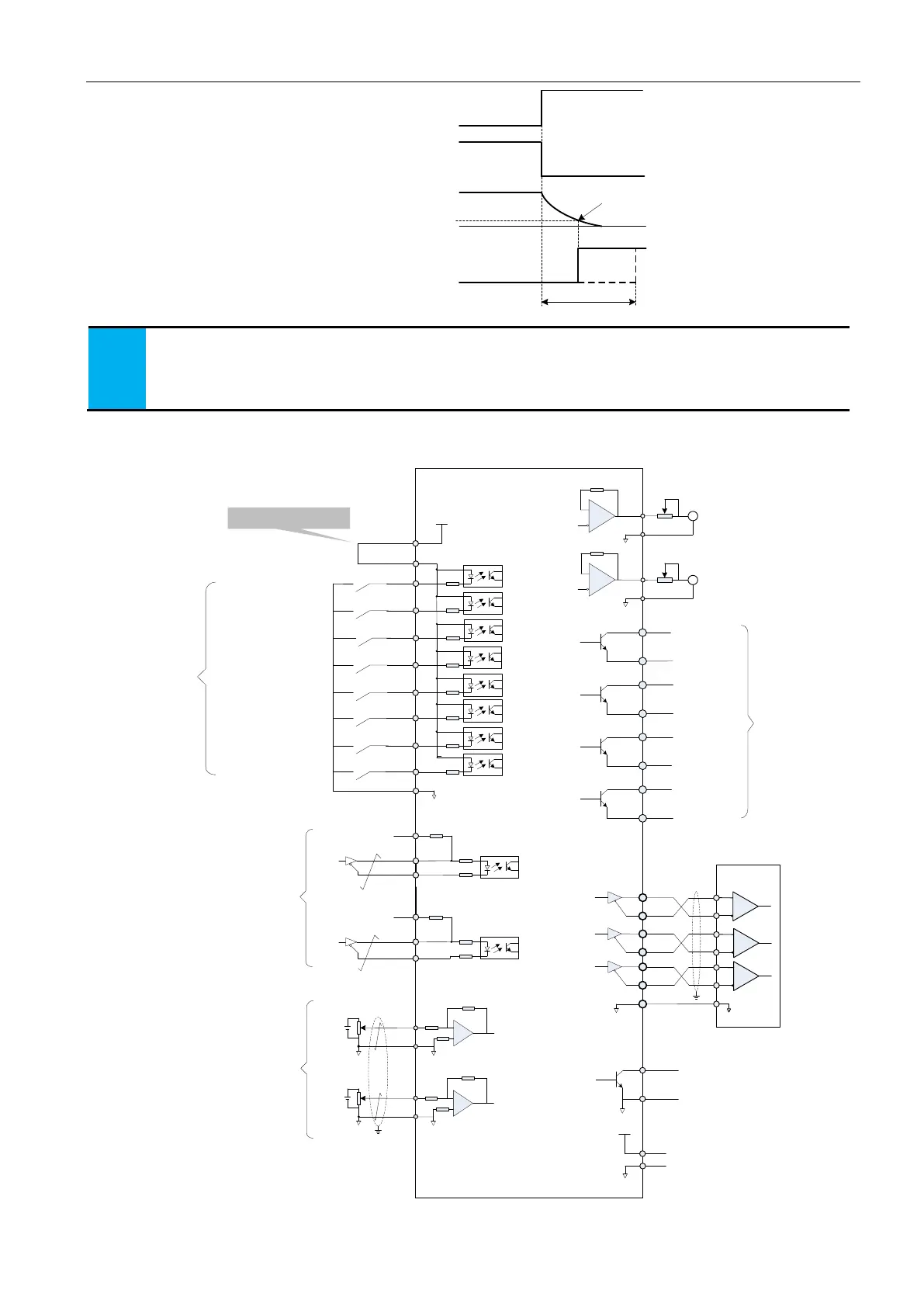
3.8 Control circuit standard wiring diagram
3.8.1 position control mode standard wiring diagram
100Ω
PULSE+
PULSE-
33
34
SIGN+
SIGN-
31
32
16
PULHIS
PULS
[CW A-ph]
SIGN
[CCW B-ph]
Position command
8
23
37
38
9
24
39
10
DO1
DO1-
DO2
DO2-
DO3
DO3-
DO4
DO4-
State output
Encoder frequency division
pulse output-differential
PE
PA+
PA-
PB+
PB-
PZ+
PZ-
28
13
12
27
26
GND
29
11
35
14
Upper
computer
GND
Encoder Z phase Open
collector output
GND
OCZ
+5V
+5V
GND
6
29
GND
AO1
Analog 1
output
Analog 2
output
15
29
30
29
GND
GND
AI2
AI1
1
EA180
servo drive
Servo ready
Brake output
Position
comparison
Fault output
Torque limiting
PE
Torque limiting: 0~10V
Input impedance: about 9kΩ
Torque limiting:-10~0V
Input resistance:about 9kΩ
Internal +5V power,
the max. allowable
current 200mA
PULHIP
+24V
+24V supply
25
COM+
21
DI1
5
DI2
20
4
DI3
19
3
18
2
DI4
DI5
DI6
DI7
17
DI8
ALM-RST
N_OT
P_CLR
INHIBIT
GNUMO
GNUM1
S-ON
P_OT
CO
M
State input
Internal +24V supply
7
Servo enabled
Alarm reset clear
Pulse error counter clear
Pulse inhibit
Prohibit positive drive
Prohibit negative drive
Electronic gear ratio
numerator selection 0
Electronic gear ratio
numerator selection 1
S-RDY
BK
COIN
ALM
2KΩ
2KΩ
A
GND
AO1
A
100Ω
100Ω
100Ω
 Loading...
