EA180 Servo Drive Manual
19
The pulse command can be input by an open collector circuit or a differential mode. The maximum input pulse frequency of the
differential input mode is 500Kpps, and the maximum input pulse frequency of the open collector circuit is 200Kpps.
The pulse input terminal needs to set a certain filtering time to prevent the interference signal from entering the servo drive, resulting
in misoperation of the motor. For filtering time, see the description of P1-15 function parameters.
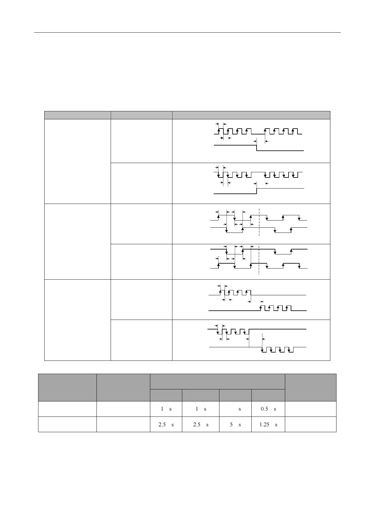
Different command input pulse patterns have different timing and time parameters
Table 3-7 Timing table for different command pulses
PULSE
SIGN
T3
T2
forward
reverse
T1
PULSE
SIGN
T3
T2
forward
reverse
T1
Two-phase orthogonal pulse
(4 octave)
PULSE
SIGN
T4 T4
forward
T4
T4
reverse
reverse
PULSE
SIGN
T4
T4
T4
T4
forward
PULSE
SIGN
T3
T1
T2
forward reverse
forward
reverse
PULSE
SIGN
T3
T1
T2
Table 3-8 Pulse input time parameter
The minimum allowable width
 Loading...
