EA180 Servo Drive Manual
51
The 3 parameters, P1-08, P1-10, and P1-12, are useful only if they require electronic gear ratio switching.
The relationship between P1-02, P1-04, and P1-06, the function of (P1-08, P1-10, P1-12) is similar to that of P1-04.
Command input and motor output
(1) Command pulse input x
-Position command
(2) Command pulse input x
-Position command
(3) Command pulse input x
-Position command
When a variety of different electronic gear ratios are required in use:
Use communication to modify P1-04 and P1-06 online (pay attention to using RAM address, otherwise it will damage the
storage device of drive);
by setting two DI terminals as 20 (GNUM0) and 21 (GNUM1)function, and then switch through the external DI input,at this
time, the numerator of the electronic gear ratio corresponding to the DI terminal state is shown as follows (0 terminal
invalid, 1 effective):
Effective electronic gear
ratio numerator
When using an external terminal to switch the electronic gear ratio, the electronic gear denominator is a fixed value, so in this
manner, be careful to select the appropriate value for P1-06.
1. P1-02 and the electronic gear ratio are effective for both the external pulse command and the internal multiple
preset position command.
2. the electronic gear ratio can be set to: 1/1000~64000/1. Beyond the Range, the drive will give Al032 alarm.
External pulse command smooth filtering time
Parameter function: the time constant of smoothing filtering of the external pulse command signal, does not work when set to 0.
The function of this parameter is to smooth the input pulse command,
but there is a delay in command.
Generally used for:
Upper computer has no acceleration and deceleration function;
The electronic gear ratio is relatively large;
The low frequency of command;
Step jump, unstable phenomenon appears when the motor is running
etc..
In order to reduce the vibration caused by the abrupt change of the command pulse frequency, there is also the
position FIR filter (P5-23) function that can be used.
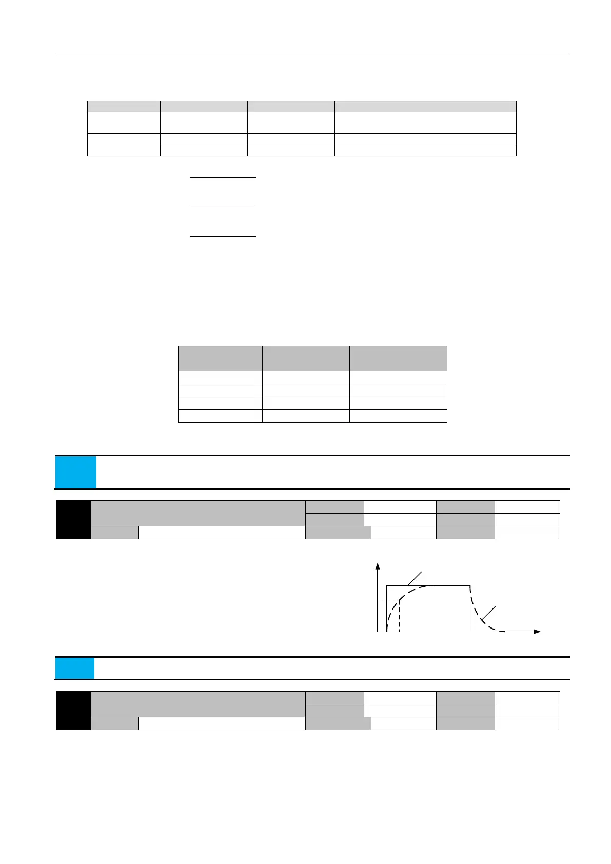
External pulse input high frequency filtering time
Parameter function: setting the time constant of the external pulse command input for high frequency filtering
When a pulse is given at a given position, a high frequency interference may occur for various reasons, resulting in an error in
the number of pulses received by the servo drive. Proper setting of this parameter can avoid high frequency interference.
If the pulse input filter time constant is Tf, the minimum width of the input signal is Tmin, then the input signal and filtered
signal are shown in the following figure. The filtered signal will delay Tf than the input signal.
Pulse
command
frequency
Before
filtering
After
filtering
0 t
63.2%
P1-14
 Loading...
