EA180 Servo Drive Manual
17
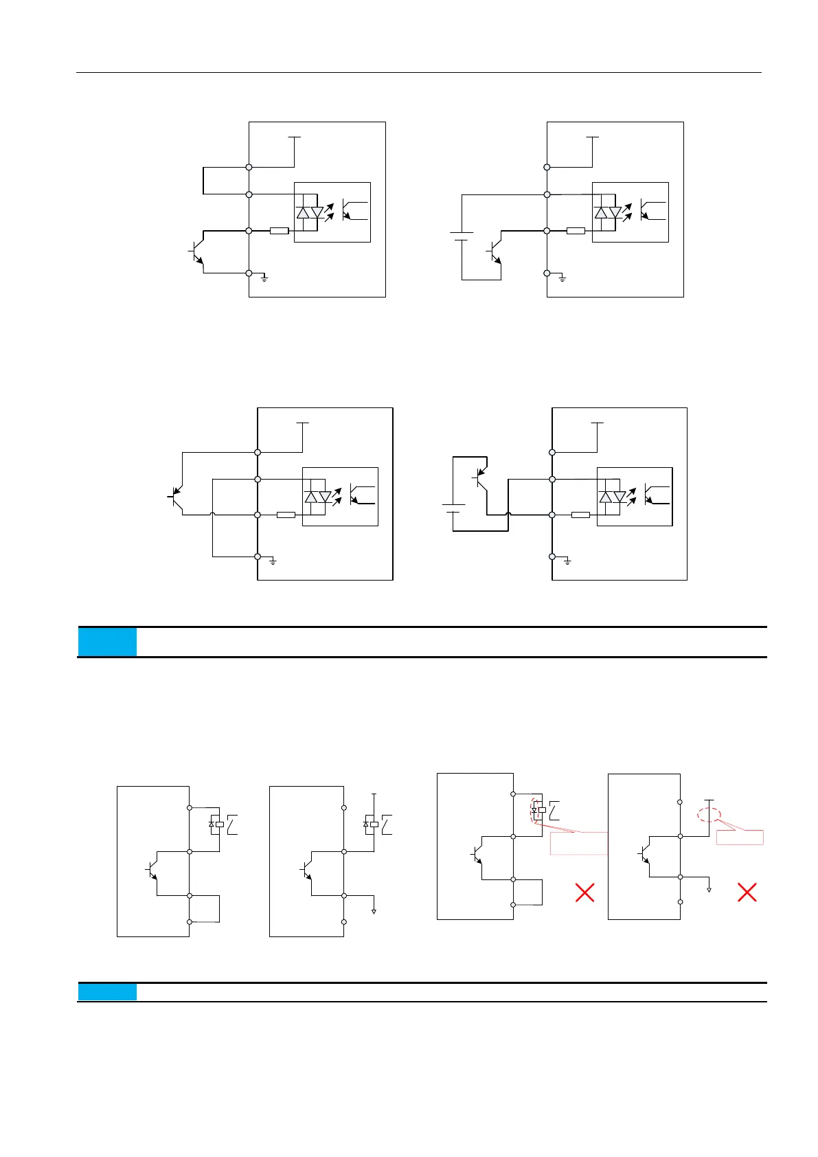
2) As for NPN open collector circuit output:
4.7K
+24V
+24V supply
COM+
DI1
COM
Internal 24V supply
Servo drive
NPN
NPN
4.7K
+24V
+24V supply
COM+
DI1
COM
External 24V supply
Servo drive
NPN
NPN
DC24V
25
21
5
7
25
21
5
7
Figure 3-9(a) NPN open collector circuit output wiring diagram
3) As for PNP open collector circuit output:
4.7K
+24V
+24V supply
COM+
DI1
COM
Internal 24V supply
Servo drive
PNP
PNP
4.7K
+24V
+24V supply
COM+
DI1
COM
External 24V supply
Servo drive
PNP
PNP
DC24V
25
21
5
7
25
21
5
7
Figure 3-9(b) PNP open collector circuit output wiring diagram
1. When using external power supply, please make sure 24V and COM+ are in open circuit.
2. Do not support PNP and NPN mixed input
3.4.6 Digital output terminal connection
Taking DO1 as an example, the interface circuit of DO1 ~ DO4 is identical.
1) When the upper device is relay:
DC5V~24V
NPN
r
e
l
a
y
Servo drive
DO1
DO1-
8
37
Internal supply
25
+24V
COM
22
NPN
r
e
l
a
y
Servo drive
DO1
DO1-
8
37
25
22
External supply
NPN
DC5V~24V
DO1
DO1-
No relay
8
37
25
22
NPN
relay
Servo drive
DO1
DO1-
8
37
25
+24V
COM
22
fly-wheel diode
polarity error
Servo drive
Figure 3-10(a) Relay input, the correct DO terminal wiring
Figure 3-10(b) Relay input, the wrong DO wiring
When the upper device is a relay input, be sure to access the fry-wheel diode, otherwise it may damage the DO port
 Loading...
