EA180 Servo Drive Manual
23
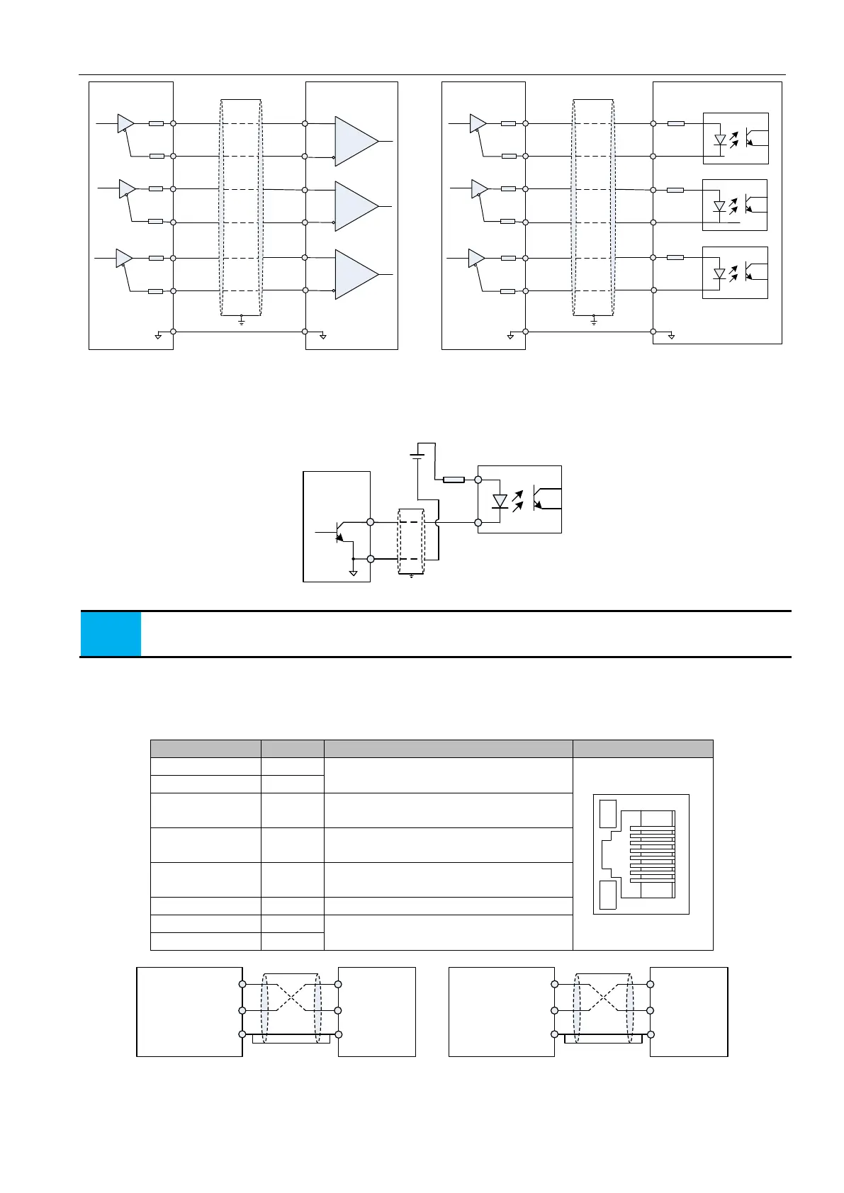
28
PA-
GND
PA+
Differential receive
PB+
PB-
PZ+
PZ-
Upper
computer
13
12
27
11
26
14
GND
28
PA-
GND
PA+
Optocoupler receive
PB+
PB-
PZ+
PZ-
Upper
computer
13
12
27
11
26
14
GND
PE
PE
Servo drive
Servo drive
Figure 3-17 Frequency division output wiring diagram
Encoder Z-phase frequency division circuit can provide a feedback signal by open collector output signal when the drive and the
host device constituting the position control system. In the upper computer device, please use a relay or optocoupler receive as circuit
receive. The maximum output current is 40mA.
Servo drive
35
DC5V~24V
OCZ
42
GND
GND
PE
Figure 3-18 OCZ terminal circuit
Please be sure that the upper computer signal supply ground is connected to the drive GND, and using the twisted
pair shielded cable to reduce noise interference.
The maximum voltage of the internal triode is 30VDC, and the maximum allowable input current is 40mA.
3.5 CN2、CN3 communication terminal wiring
The drive is connected to the host computer by two same communication signalconnectors CN2 and CN3 connectors in parallel
with each other. The user can use MODBUS communication to operate the drive, and the communication distance is about 15m.
Communication Connector Pin Description
RS485,RS232 Communication
Reference ground
The sender of RS232 is connected with the
receiver of upper computer
The receiver of RS232 is connected with the
sender of upper computer
CAN Communication Reference ground
RS485-
Servo drive
RS485+
GND
Upper computer
RS485 interface
+ Terminal
- Terminal
GND
RS232-TXD
RS232-RXD
GND
Upper computer
RS232 interface
TXD
RXD
GND
Servo drive
Figure 3-19 communication port diagram
 Loading...
