EA180 Servo Drive Manual
8
3.2 Main circuit terminal connection
The main circuit (high voltage part) terminal arrangement and screw dimensions are as follows.
3.2.2 The main circuit (high voltage part) terminal description
Table 3-1 Description of main circuit terminal of servo drive
Control power input terminal
1-phase input voltage class is the same as the main circuit power
Main circuit AC power
input terminal
EA180-1R6-2□
EA180-2R8-2□
EA180-5R5-2□
EA180-7R6-2□
L1、L2 1-phase 220V input
Or L1、L2、L3 3-phase 220V input
L1、L2、L3 3-phase 220V input
EA180-5R4-3□
EA180-□□□-3□
EA180-026-3□
External braking resistor
connection terminal
The default connection between P+ and D is short wiring. When the braking
capacity is insufficient, please open the circuit between P+ and D, and
connect the external braking resistor between P+ and C.
The DC bus terminal of the servo drive can be connected in parallel when
the multiple drives are in operation.
Servo motor
connection terminal
The connecting terminals of the servo motors are connected with U, V and
W of the motor.
EA180-2R8-2□、EA180-5R5-2□ one ground terminal; connect with the two
ground terminals of other power size, power supply and motor ground
terminal.
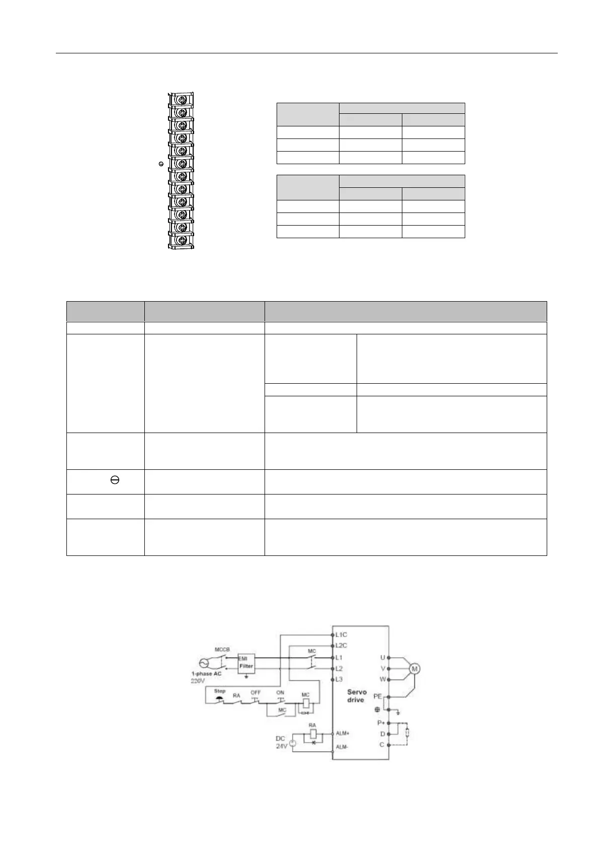
3.2.3 Power connection
Servo drive power supply wiring method is divided into single-phase and three-phase respectively, single-phase only suitable
for the output current of 7.6A and below models.
Single phase power supply wiring method (rated output current 7.6A and below applicable)
Figure 3-1 1-phase power supply connection
 Loading...
