EA180 Servo Drive Manual
16
3.4.4 Digital output function definition( DO)
Effective- servo ready to receive S-ON command
Invalid - the servo is not ready and does not receive the S-ON
command
Effective-brake disengaged
Invalid-brake engaged
Effective - the motor is rotating (RPM is higher than the P0-04 setting)
Invalid - motor stop rotating (speed below P0-04 setting)
Effective - motor speed is zero (speed lower than P0-03 setting)
Invalid - motor speed is not zero (RPM is higher than P0-03 setting)
Effective: when in speed control, the actual speed of the motor reaches
or exceeds the setting value of the P2-08 (regardless of direction).
Effective: When in speed control, the absolute difference between the
actual speed and the speed of the motor is less than P2-09
Effective: In position control mode, the position deviation pulse is less
than the setting value of the positioning approach width P1-23
Effective: In position control mode, the position deviation pulse is less
than the positioning completion width, the P1-24 setting value, and the
condition of the P1-22 definition is satisfied.
Effective: motor torque limited
Invalid: motor torque is not limited
Effective: motor speed is limited
Invalid: motor speed is not limited
Effective: warning happens
Effective: motor output torque reaches set point
Invalid: motor output torque is not up to set point
Effective: Homing finishes
Invalid: Homing is in the process
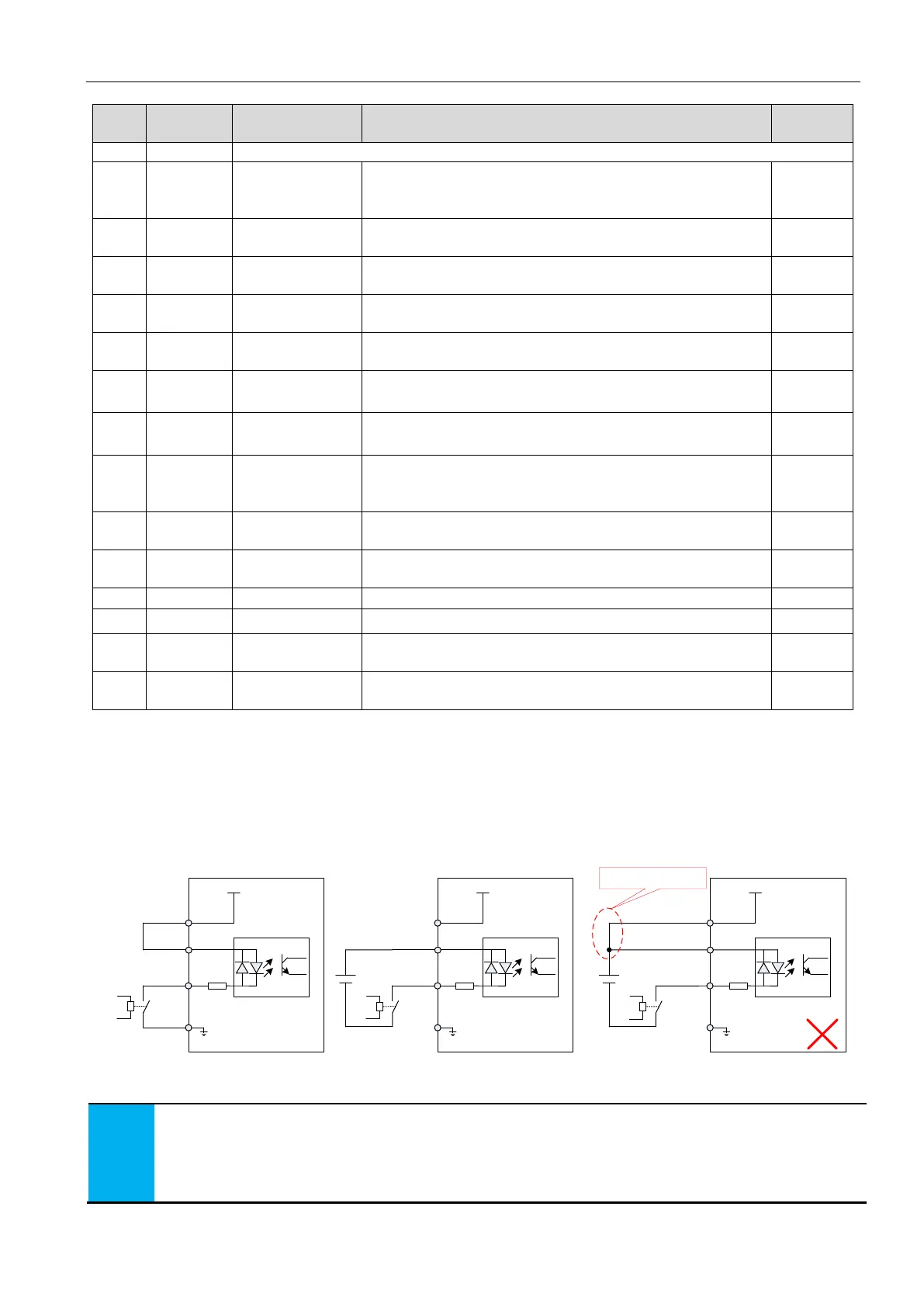
3.4.5 Digital input terminal connection
The digital (DI) input terminal of the EA180 series servo drive uses a full bridge rectifier circuit. The current flowing through the
terminals can be either positive (NPN mode) or negative (PNP mode).
Taking DI1 as an example, the interface circuit of DI1 ~ DI8 is identical.
1) When the upper device is the relay output:
4.7K
+24V
+24V supply
COM+
DI1
relay
COM
Internal 24V supply
4.7K
+24V
+24V supply
COM+
DI1
relay
COM
External 24V supply
DC24V
4.7K
+24V
+24V supply
COM+
DI1
COM
Servo drive Servo drive
Not use 1-phase power
25
21
5
7
25
21
5
7
25
21
5
7
relay
DC24V
Figure 3-8 when the upper device is relay output, digital input terminals wiring
Defaulted setting:
The COM terminal used pin #7 , pin# 22/36 is also applicable.
The GND terminal used pin #14, also pin# 29 is applicable.
The servo internal +24V used pin# 25, also pin # 40 is applicable.
 Loading...
