EA180 Servo Drive Manual
22
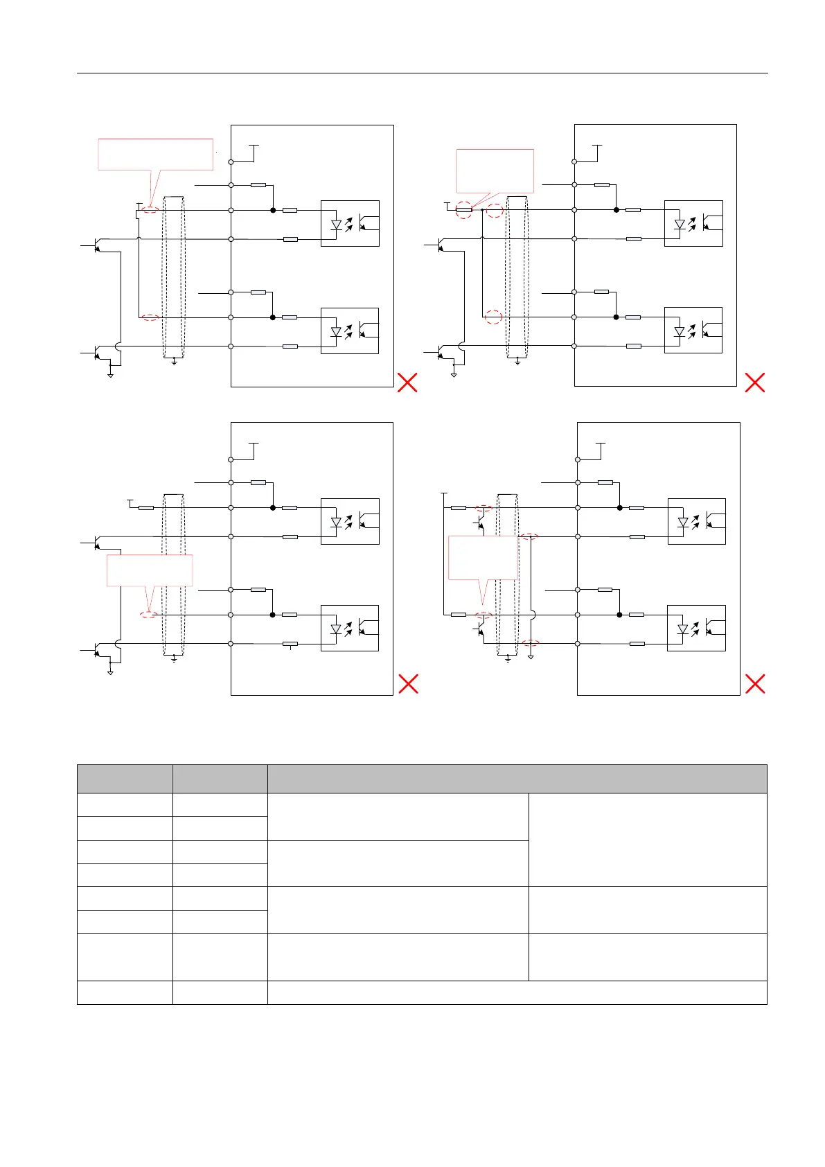
Typical examples of mis-connection
2KΩ
100Ω
100Ω
1
33
34
100Ω
100Ω
31
32
16
PULSE+
SIGN-
COM
+24V
PULHIP
PULHIS
25
SIGN+
PULSE-
Servo drive
PE
VCC
Current limiting
resistance not connected
2KΩ
100Ω
100Ω
1
33
34
100Ω
100Ω
31
32
16
PULSE+
SIGN-
COM
+24V
PULHIP
PULHIS
25
SIGN+
PULSE-
Servo drive
PE
VCC
Current limiting
resistance not
separately used
2KΩ
2KΩ
2KΩ
100Ω
100Ω
1
33
34
100Ω
100Ω
31
32
16
PULSE+
SIGN-
COM
+24V
PULHIP
PULHIS
25
SIGN+
PULSE-
Servo drive
PE
VCC
R1
Not connected to
SIGN signal
2KΩ
100Ω
100Ω
1
33
34
100Ω
100Ω
31
32
16
PULSE+
SIGN-
+24V
PULHIP
PULHIS
25
SIGN+
PULSE-
Servo drive
PE
VCC
OC signal not
connected to
the port
COM
2KΩ 2KΩ
3.4.9 CN4 encoder output frequency division circuit
Table 3-9 Encoder frequency division output signal description
A Phase frequency division output signal
A,B orthogonal frequency pulse output
signal
B Phase frequency division output signal
Z Phase frequency division output signal
Origin pulse output signal
Z Phase frequency division output signal
Origin pulse open collector output
signal
Origin pulse open collector output signal ground
Encoder frequency division circuit output differential signals by a differential drive. Generally, it will provide a
feedback signal when the drive and the host device constituting the position control system. In the upper computer
device, please use a differential or optocoupler receive as circuit receive. The maximum output current is 20mA.
 Loading...
