EA180 Servo Drive Manual
52
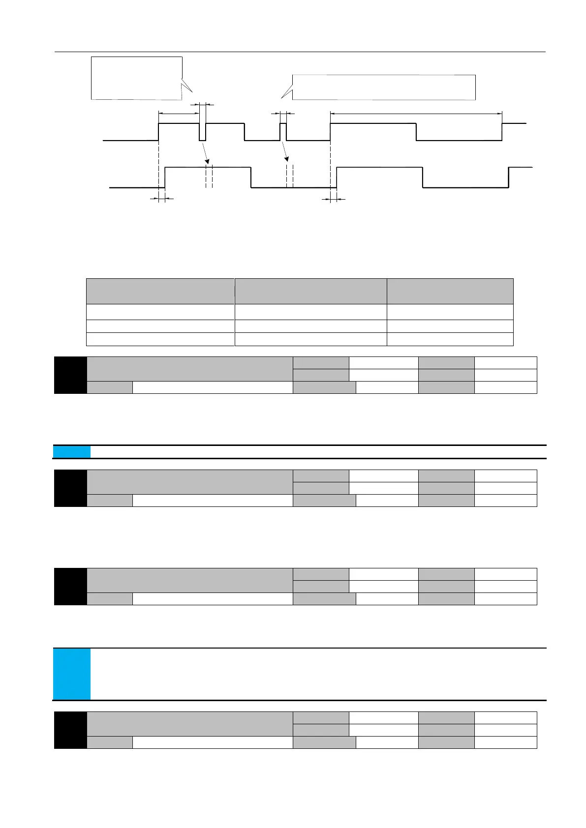
>T
f
<T
f
T
f
T
f
The minimum width of the input signal Tmin
Input signal
Filtered signal
The signal width is less
than Tf, after filtering,
the original high level
state is maintained
<T
f
The signal width is less than Tf, after filtering,
the original high level state is maintained
Figure 5-8 Example of pulse input signal filtering
Pulse input filter time constant Tf should meet: Tf = (20%~25%) Tmin
The maximum frequency (or minimum pulse width) of a given input pulse signal. The recommended filtering time parameters are
shown in the table below:
Maximum frequency of input pulse
Recommended parameters for P1-15
Position deviation clear external DI signal action
Parameter function: select what kind of external DI signal to clear the deviation.
P1-16=0: cleared by rising edge of P-CLR
P1-16=1: clear through P-CLR low level
P1-16=2: clear by P-CLR high level
P1-16=3: cleared by falling edge of P-CLR
The position deviation will be automatically cleared when the servo is enabled to turn off or alarm occurs.
Position following deviation threshold alarm
Parameter function: set the position follow deviation warning threshold.
When the position deviation reaches and is greater than the set point, output warning against too large position following
deviation warning signal too large.
The motor continues, and the LED monitor displays AlE05, defined as the valid output of the DO terminal of the WARN. Once
the position deviation is less than the set point, the warning is cancelled automatically.
Position following deviation alarm threshold
Parameter function: set position following error alarm threshold.
When the position deviation reaches and is larger than the corresponding setting value, output warning against too large
position deviation.
When the motor stops, LED display reads Al013,defined as DO terminal of ALM effective.
1. when P1-18=0, the position following deviation warning is blocked. When P1-20=0, the position deviation is too large
and the alarm is blocked.
2. the setting unit at the factory is the command unit, but can be changed to the encoder unit through the P8-18 bit3.
When using the encoder unit, please set the appropriate value according to the resolution of the encoder to avoid
frequent alarms due to the small set value.
Positioning completion output setting
Parameter function: select the output effective condition for the positioning completion signal (defined as the DO terminal of the
COIN) to output valid conditions.
 Loading...
