EA180 Servo Drive Manual
21
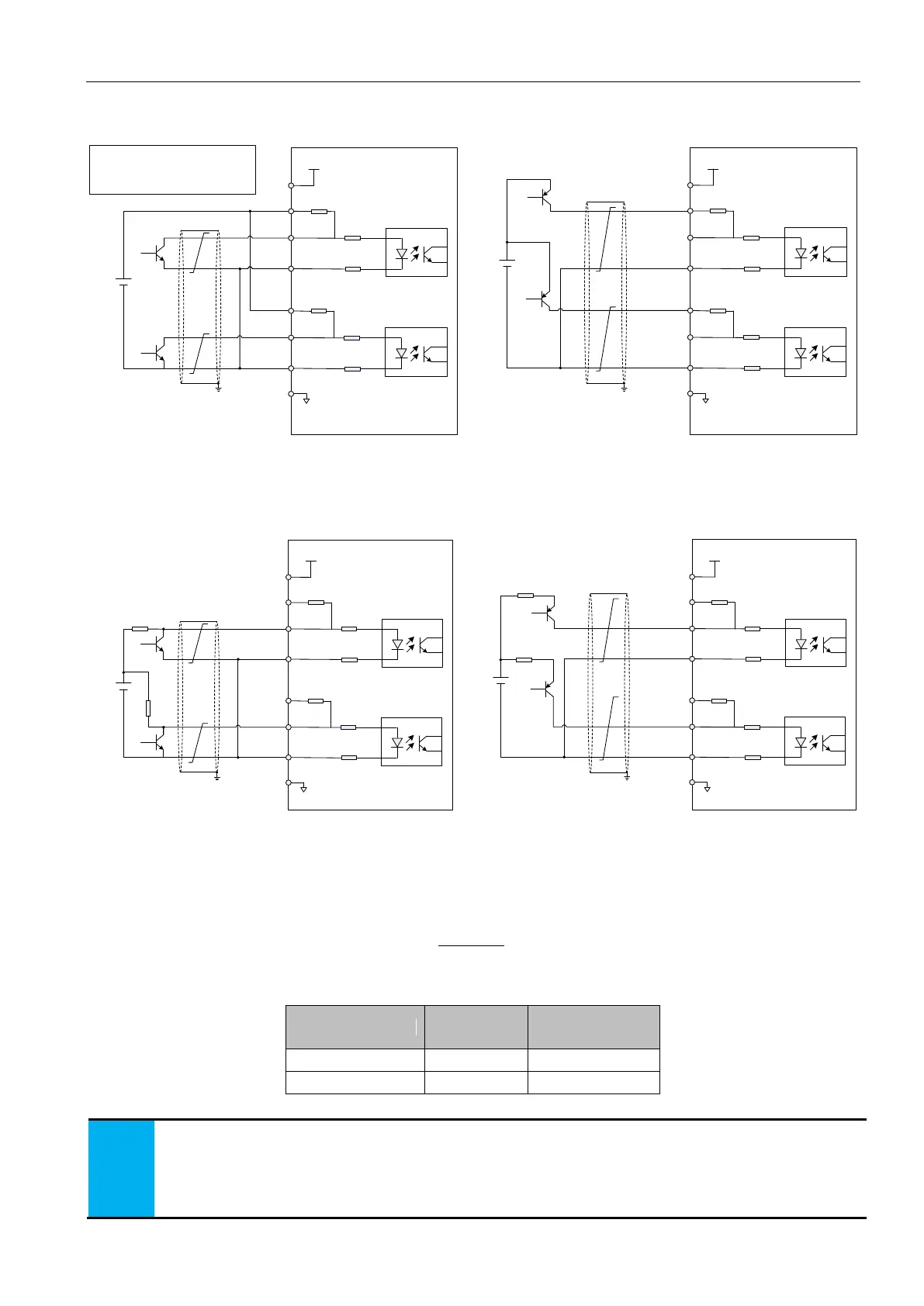
When using the external 24V power supply and internal current limiting resistance
+24V
Extl
2KΩ
100Ω
100Ω
1
33
34
100Ω
100Ω
31
32
36
16
PULSE-
SIGN-
COM
+24V
PULHIP
PULHIS
+24V
Servo drive
PULSE+
PE
External 24V supply and internal current
limiting resistor NPN connection
External 24V supply and internal current
limiting resistor PNP connection
Open collector pulse position command
The maximum input frequency is
200kpps
Minimum pulse width 2.5us
25
2KΩ
SIGN+
2KΩ
100Ω
100Ω
1
33
34
100Ω
100Ω
31
32
36
16
PULSE-
SIGN-
COM
+24V
PULHIP
PULHIS
+24V
Servo drive
PULSE+
PE
25
2KΩ
SIGN+
+24V
Extl
Figure 3-15(a) open collector pulse input command wiring diagram (using external power supply and external limiting resistor)
Wiring method of external 24V power supply and external current limiting resistance
+24V
Ex.
2KΩ
100Ω
100Ω
1
33
34
100Ω
100Ω
31
32
36
16
PULSE-
SIGN-
COM
+24V
PULHIP
PULHIS
+24V
Servo drive
PULSE+
PE
NPN wiring method
PNP wiring method
25
2KΩ
SIGN+
2KΩ
100Ω
100Ω
1
33
34
100Ω
100Ω
31
32
36
16
PULSE-
SIGN-
COM
+24V
PULHIP
PULHIS
+24V
Servo drive
PULSE+
PE
25
2KΩ
SIGN+
+24V
Ex.
R1
R1
R1
R1
Figure 3-15(b) Open collector mode input pulse command wiring diagram(external 24V suppply)
Selection of current limiting resistance R1:
R1:
R1 recommended resistance:
1. a pair of differential signals, be sure to use a pair of twisted pairs.
2. pulse input signal cable must be separated from power cable, at least 30cm or more away from each other.
3. because the pulse input interface is not shielded from the input interface, in order to reduce noise interference, it is
suggested that the output signal of the upper computer is connected to the signal ground of the drive
 Loading...
