EA180 Servo Drive Manual
9
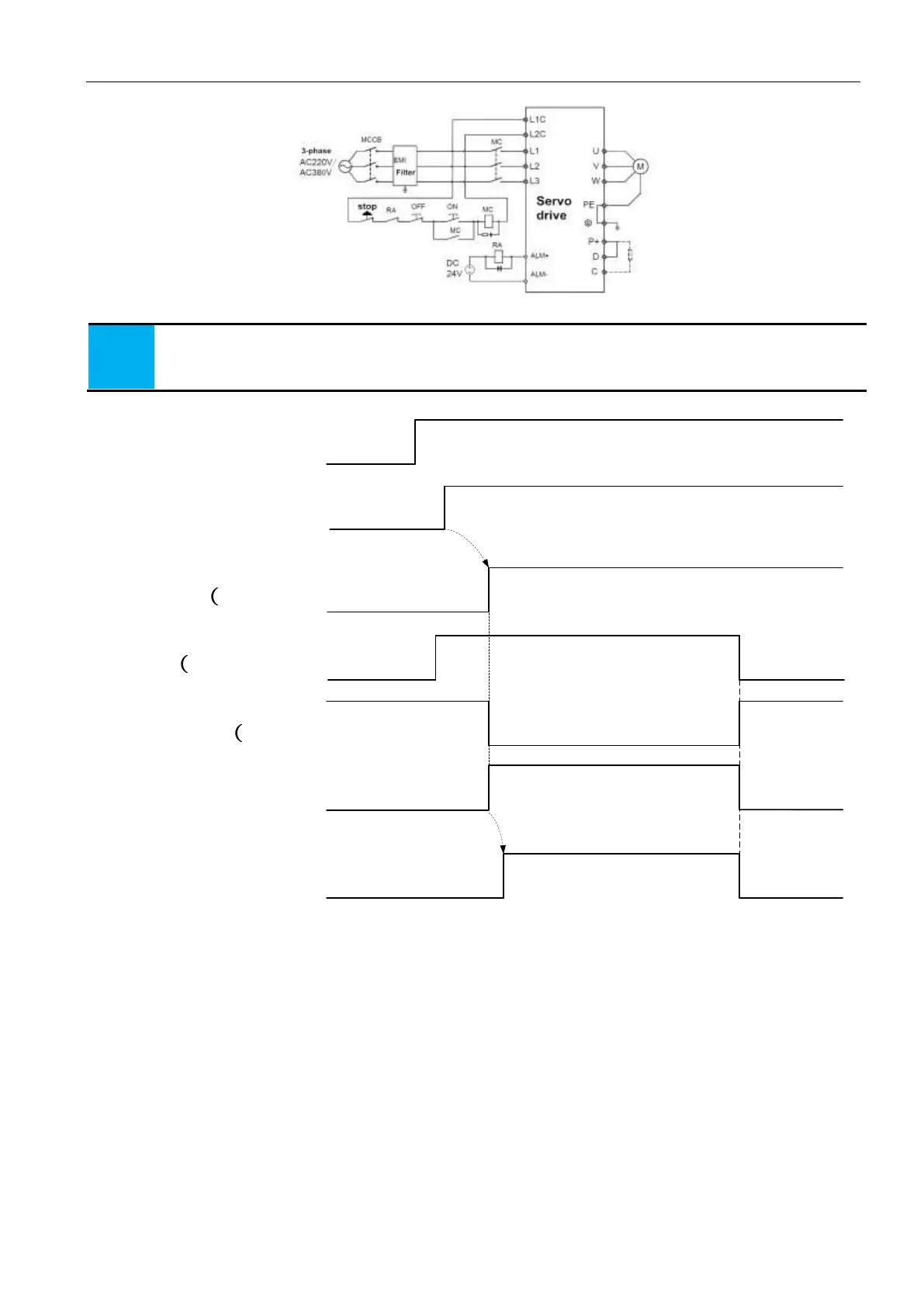
Three phase power supply wiring method (all series are applicable)
3-phase power supply connection
1. 1. if you do not want to cut off the main loop power supply when a fault occurs, you do not need to use the RA
relay.
2. 2., L1C, L2C can also be not used with external power supply, but they are connected to P+ - - terminals (No
need to distingh polarity).
3.2.4 Power on timing sequence
Control circuit supply
Main circuit supply
Servo ready output
S-RDY)
Servo enabled
S-ON)
Servo motor excitation
Power off
power on
Power off
power on
Power off
ready
enabled void
command not received
motor power off
motor power on
command not received
command received
Position/speed/torque
command
delay 1.5S
delay P0-16time
Servo enabled signal
S-ON signal)
void
valid
void
enabled void
motor power off
enabled valid
Figure 3-3 Power-on timing diagram
For power connections, refer to Figure s 3-1 and 3-2 and turn on the power supply in the following order:
1) the power supply L1C and L2C of the control circuit must be connected in the same time or before the main loop supply is
connected. If the power of the control circuit is connected only, the servo ready signal (S-RDY) will not be effective.
2) the power supply is connected to the main circuit power input terminal (three-phase connected L1, L2, L3, single phase L1 and
L2) by electromagnetic contactor.
3) when the main circuit is connected, the delay time is about 1.5 seconds, and the servo ready signal (SRDY) is effective and
receive the servo enabled signal (S-ON) at this time. When the servo enable signal is detected, the motor is excited and in the running
state. If the servo is disabled or has an alarm, the drive output is switched off and the motor is in a free state.
4) when the servo is switched on with the power supply, the motor is excited about 1.5 seconds later.
5) frequent switching on and off the main circuit power, may damage the soft start circuit and the energy consumption brake circuit,
the frequency of switching on is best limited to 5 times per hour, 30 times a day below. If the drive unit or the motor is overheating, after
the cause of the failure is ruled out, reconnect the power supply after 30 minutes of cooling.
6) Do not connect the input power line to the output terminals U, V, and W, otherwise it will damage the servo drive.
7) the braking resistance is absolutely prohibited from connecting between the DC bus P+ and the terminals, otherwise it may cause
a fire.
8) after the power is switched off, there may be residual voltage on the internal capacitor of the servo drive. Please confirm that the
CHARGE indicator on the servo driver panel is extinguished before checking the operation.
Specification for connector of motor power cable
 Loading...
