EA180 Servo Drive Manual
18
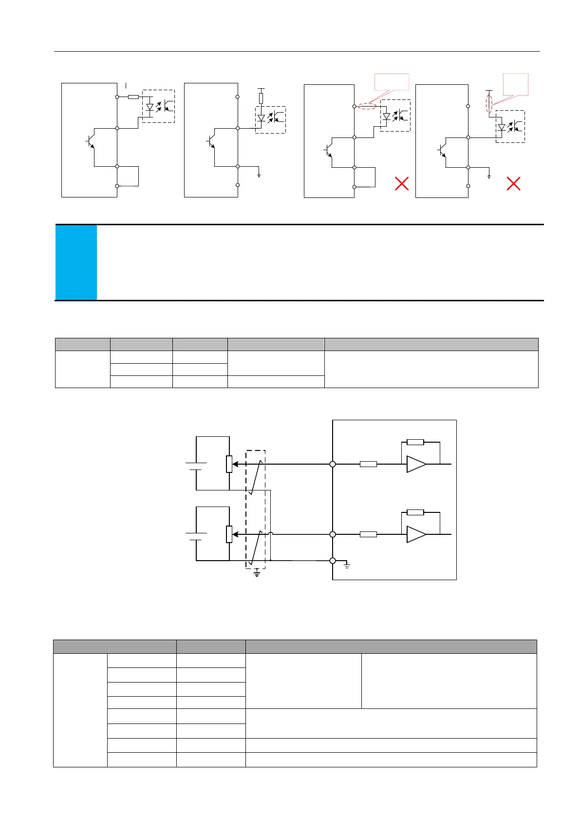
2) When the uppder device is optocoupler input
NPN
DC5V~24V
Servo drive
DO1
DO1-
8
37
NPN
Servo drive
DO1
DO1-
8
37
Internal supply External supply
25
+24V
COM
22
25
COM
22
External
supply
ground
NPN
DC5V~24V
Servo drive
DO1
DO1-
8
37
NPN
DO1
DO1-
8
37
Internal supply External supply
25
+24V
COM
22
25
COM
22
No current
limiting resistor
No current
limiting
resistor
External
supply
ground
Servo drive
Figure 3-11(a) Optocoupler input, correct DO port wiring
Figure 3-11(b) Optocoupler input, wrong DO port wiring
Servo drive internal optocoupler output circuit, maximum allowable voltage and current capacity are as follows:
voltage:DC30V(max.)
current:DC50mA(max)
As for inductive loads (e.g. relays and Contactors), should be equipped with surge absorption circuit; such as: RC
absorption circuit (note the leakage current shall be less than that of the control contactor or relay current), varistors,
or diode etc. (for DC magnetic circuit, must pay attention to the polarity when installing). The component of the
absorption circuit is to be mounted near the coil of the relay or contactor.
3.4.7 CN4 analog input terminal wiring
Voltage input range: -10V to +10V, resolution 12 bits
Maximum allowable voltage: ±12V
Input impedance: 10K
AI1、AI2 is generally used for speed or torque analog signal input.
-10~+10V
AI1
-10~+10V
AI2
About 9K
About 9K
Servo drive
GND
15
30
29
Figure 3-12 AI1、AI2 terminal wiring
3.4.8 CN4 position command input signal
The position command pulse input signal and the command symbol input signal terminal in CN4 terminal are described below.
Table 3-6 Position pulse input signal description
Pulse command input mode:
Differential input
Open collector input
Input pulse mode:
Direction + pulse
A and B phase orthogonal pulses
CW/CCW pulse
Command pulse external power input interface
 Loading...
